
Method for converting non-manifold CAD software based on boundary representation

A technology of boundary representation and conversion method, which is applied in the field of conversion between non-manifold CAD software, and can solve problems such as inability to complete the conversion

Active Publication Date: 2021-09-14
GUANGDONG UNIV OF TECH
View PDF8 Cites 2 Cited by
  • Summary
  • Abstract
  • Description
  • Claims
  • Application Information

AI Technical Summary

Problems solved by technology

[0003] For the non-manifold solid model, the special file interface and the neutral file interface can satisfy the conversion, but the conversion method of the non-manifold solid model based on the BRep interface cannot complete the conversion

Method used


Image

  • Method for converting non-manifold CAD software based on boundary representation
  • Method for converting non-manifold CAD software based on boundary representation
  • Method for converting non-manifold CAD software based on boundary representation

Examples


Embodiment Construction

[0032] The structure of the non-manifold model is used to construct the Body of Parasolid, and the Body in Barasolid is divided into four types, as shown in the following table:

[0033] Body describe Minimum_body isolated point Wire_body A set of connected edges, with no more than 2 edges connected by any vertex Sheet_body A set of connected faces where each edge connects at most two faces Solid_body a solid region (e.g. a cube)

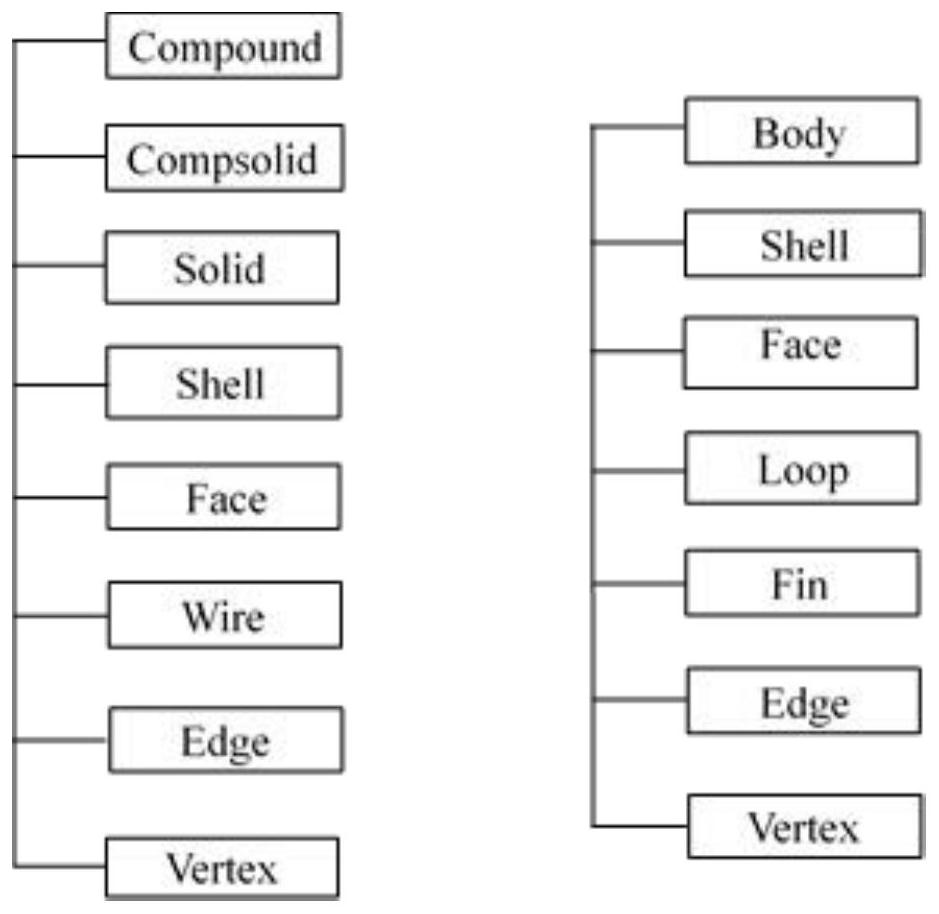
[0034] OpenCascade's topology model tree such as figure 2 As shown in the left view, Compound (mixed) is a combination of any type of Compsolid, Solid, Shell, Face, Wire, Edge, and Vertex; Compsolid is a combination of a group of Solid (stereo) entity types, and Solid topological entities represent three-dimensional closures The geometric entity itself, the boundary of Solid is expressed by one or more Shell (shell) topological entities, the boundary of Shell is expressed by one or more Face (surface) top...


PUM


Abstract

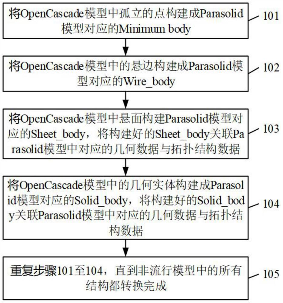
The invention discloses a method for converting non-manifold CAD (Computer Aided Design) software based on boundary representation. The method comprises the following steps of: constructing isolated points in an OpenCascade model into a Minimum body corresponding to a Parasolide model; constructing a dangling edge in the OpenCascade model into a Wire_body corresponding to the Parasolid model, wherein the Wirebody is used for constructing the dangling edge in the OpenCascade model; constructing a Sheet_body corresponding to a Parasolid model for a suspension surface in an OpenCascade model, and associating the constructed Sheet_body with corresponding geometric data and topological structure data in the Parasolid model; constructing a geometric entity in the OpenCascade model into a Solid_body corresponding to the Parasolid model, and associating the constructed Solid_body with corresponding geometric data and topological structure data in the Parasolid model; and repeating the steps until all structures in the non-popular model are converted. According to the method, the boundary expression BRep of the OpenCascade and the Parasolide geometric core is directly extracted, and then the mapping relation between the BRep is established, so that data conversion between CAD systems is completed, the conversion adaptability between software is higher, and the relative stability is higher.

Description

technical field [0001] The present application relates to the technical field of file conversion, in particular to a conversion method between non-manifold CAD software based on boundary representation. Background technique [0002] The traditional methods to solve the information exchange between CAD software adopt the method of special file interface, neutral file interface and interface method based on BRep (Boundary Representation, boundary representation). The method of special file interface refers to the development of a file interface for mutual conversion of data formats between two different CAD software. The neutral file interface method refers to information exchange through several recognized intermediate file formats. Typical neutral files include IGES neutral files supported by most software, STEP neutral files adopted by the International Organization for Standardization, etc. The method based on the BRep interface refers to using the boundary expression BRe...

Claims


Application Information

Patent Timeline
Patent Type & Authority Applications(China)
IPC IPC(8): G06F8/51
CPCG06F8/51
Inventor 刘海涛黄运保李海艳
Owner GUANGDONG UNIV OF TECH
Learn More