Refractive index change sensing device and measuring method

A refractive index change, refractive index technology, applied in the field of devices based on refractive index change sensing

Active Publication Date: 2021-09-14
CHONGQING UNIV OF POSTS & TELECOMM
View PDF9 Cites 1 Cited by
  • Summary
  • Abstract
  • Description
  • Claims
  • Application Information

AI Technical Summary

Problems solved by technology

However, this detection technique requires the ...

Method used


Image

  • Refractive index change sensing device and measuring method
  • Refractive index change sensing device and measuring method
  • Refractive index change sensing device and measuring method

Examples


Embodiment

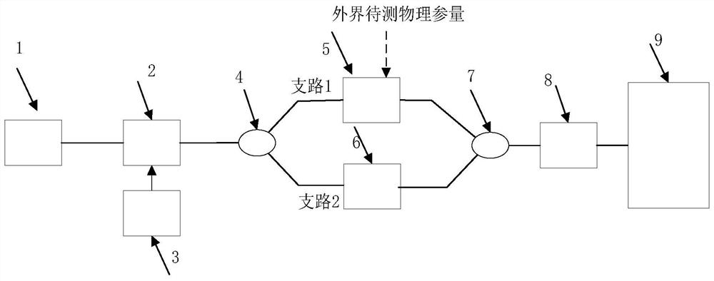
[0047] figure 1 It is a schematic structural diagram of the sensing device based on the refractive index change of the present invention. The optical carrier output by the laser 1 is input into the suppressed carrier double sideband modulation module 2, and the microwave signal sent by the microwave source 3 is loaded onto the optical carrier through the suppressed carrier double sideband modulation module 2, and the modulated optical carrier output by the suppressed carrier double sideband modulation module 2 is loaded. It is divided into branch 1 and branch 2 by beam splitter 4 . In branch 1, the suppressed carrier double sideband optical signal passes through the refractive index sensitive module 5, and the refractive index sensitive module 5 is used to sense the refractive index change caused by the change of external physical parameters, so that the phase difference between the two optical sidebands is changed. In branch 2, the suppressed carrier double-sideband optical ...


PUM


Abstract

The invention relates to a refractive index change sensing device and a measuring method, and belongs to the field of optical fiber sensing. The device comprises a laser, a carrier suppression double-sideband modulation module, a microwave source, an optical beam splitter, a refractive index sensitive module, a frequency shifter, an optical coupler, a photoelectric detector and a signal acquisition and data processing module. The laser, the carrier suppression double-sideband modulation module, the optical beam splitter, the refractive index sensitive module, the frequency shifter, the optical coupler and the photoelectric detector are sequentially and optically connected; the carrier suppression double-sideband modulation module and the microwave source are in circuit connection in sequence; and the photoelectric detector and the signal acquisition and data processing module are in circuit connection in sequence. According to the invention, the defects that the spectral analysis precision is low in the existing optical fiber sensing detection technology and a broadband range detection and processing system is needed in the traditional microwave photon sensing detection are overcome, and the method has the advantages of high measurement precision, real-time measurement, need of a low-frequency detection and processing system only and the like.

Description

technical field [0001] The invention belongs to optical fiber sensing technology, in particular to a device and measurement method based on refractive index change sensing. Background technique [0002] Optical fiber sensing technology has been the research focus of its research field since optical fiber technology moved from theory to practice. With the continuous development of science and technology, the requirements for sensors are getting higher and higher. Sensitivity, high precision, and small size have become the development direction of sensors. Traditional sensors are gradually unable to meet the demand due to their shortcomings such as electromagnetic interference, high temperature and high pressure, and fiber optic sensors are widely used due to their advantages of anti-electromagnetic interference, low loss, high cost performance, and safety. The basic principle of optical fiber sensing technology is that when light is transmitted in the optical fiber, the char...

Claims


Application Information

Patent Timeline
IPC IPC(8): G01D5/26G01D5/353
CPCG01D5/268G01D5/35329
Inventor 邹新海杜森阳李越豪冀涵颖王恒刘磊黎人溥郭俊启刘宇
Owner CHONGQING UNIV OF POSTS & TELECOMM
Why Eureka
Try Eureka