
Spinning machine

A technology of spinning machine and bobbin, applied in the field of spinning machine, can solve the problems of hindering spinning station, time-consuming and the like

Pending Publication Date: 2021-09-14
MASCHINENFABRIK RIETER AG
View PDF3 Cites 0 Cited by
  • Summary
  • Abstract
  • Description
  • Claims
  • Application Information

AI Technical Summary

Problems solved by technology

This is time consuming and blocks the spinning station for a very long time until the spinning station can again be attached with a new sliver

Method used


Image

  • Spinning machine
  • Spinning machine
  • Spinning machine

Examples


Embodiment Construction

[0035] In the following description of the alternative exemplary embodiment shown in the figures, the same reference numerals are used for features whose design and / or mode of operation are identical and / or at least similar. If this is not described again in detail, the configuration and / or the effect and mode of operation of the configuration correspond to the aforementioned features.

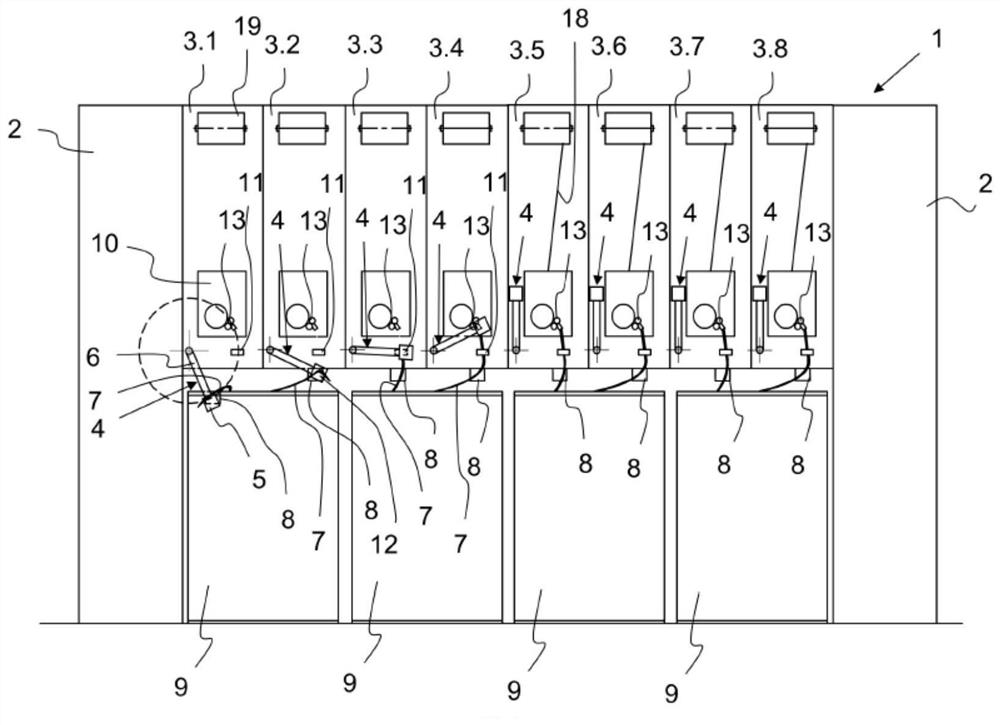
[0036] figure 1 A side view of a spinning machine 1 according to the invention, here an air spinning machine, is shown. Eight spinning stations 3.1 to 3.8 are arranged between the two end supports 2 . Several hundred such spinning stations 3.1 to 3.8 are arranged side by side per machine side in an air spinning machine. The spinning stations are usually subdivided on each machine side into closely arranged individual segments with 8 to 12 spinning stations 3.1 to 3.8 in each case. Each of the spinning stations 3.1 to 3.8 has a spinning box 10 in which a thread bundle 18 is spun and wound on...


PUM


Abstract

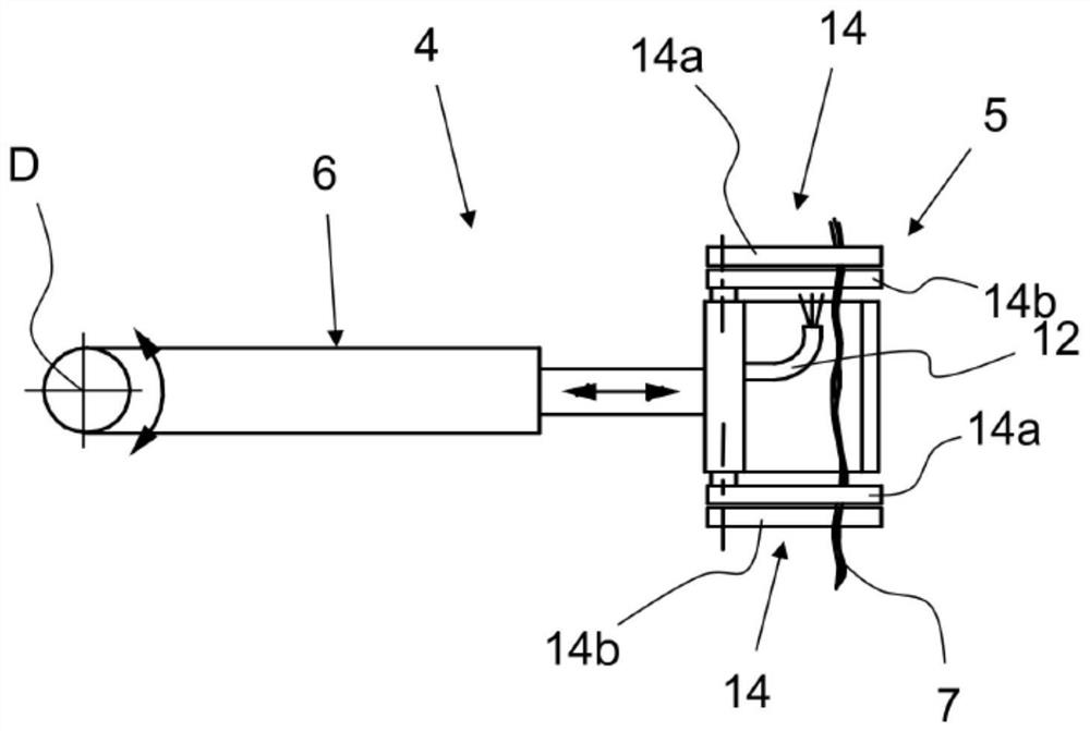
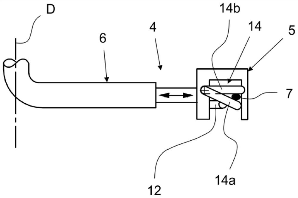
In a spinning machine having a plurality of spinning stations (3) arranged next to one another, each spinning station (3) has a feeding device (13) for a fiber bundle (7). The spinning station (3) is provided with a supporting device for the fiber bundle (7). The invention relates to a splicing device (4) for a fiber bundle (7), comprising at least one strand receiver (5) for capturing and receiving a starting part of the fiber bundle (7) and an input device (6) for conveying the starting part of the fiber bundle (7) to a feeding device (13). A splicing device (4) having a strand receiver (5) and an input device (6) is arranged at least partially stationary on the spinning machine (1), preferably on each spinning station (3), and is assigned to a respective spinning station (3) or a group of spinning stations (3).

Description

technical field [0001] The invention relates to a spinning machine having a plurality of spinning stations arranged side by side, a supporting device for a fiber bundle and a connecting device for a fiber bundle provided for the spinning station, wherein each Each spinning station has a feeding device for the fiber bundle, wherein the splicing device comprises at least one strip receiver for capturing and receiving the beginning of the fiber bundle and for feeding the beginning of the fiber bundle into the The device's input device. Background technique [0002] A maintenance device for a textile machine for fiber processing is known from DE 10 2005 009 766 A1, which has a plurality of workstations with handling devices for handling fiber sliver. The handling device takes the fiber sliver by means of a suction pipe and a mechanical and / or pneumatic holding device for the fiber sliver. The suction pipe has a flattened suction nozzle, by means of which the end of the fiber s...

Claims


Application Information

Patent Timeline
Patent Type & Authority Applications(China)
IPC IPC(8): D01H9/00
CPCD01H9/008D01H15/00
Inventor A·斯蒂芬J·劳特林格
Owner MASCHINENFABRIK RIETER AG
Learn More