Array impact structure based on circular truncated cone and cylindrical protrusion

A cylindrical and circular frustum technology, applied in the field of array impact structure, can solve the problems of large pressure loss, impact heat exchange flow reduction, etc.

Pending Publication Date: 2021-09-10
NORTHWESTERN POLYTECHNICAL UNIV +1
View PDF15 Cites 2 Cited by
  • Summary
  • Abstract
  • Description
  • Claims
  • Application Information

AI Technical Summary

Problems solved by technology

However, after the raised ribs are arranged, although the heat transfer area is increased, so the heat transfer coefficient is increased, but at the same time, a greater pressure loss is generated, s

Method used


Image

  • Array impact structure based on circular truncated cone and cylindrical protrusion
  • Array impact structure based on circular truncated cone and cylindrical protrusion
  • Array impact structure based on circular truncated cone and cylindrical protrusion

Examples


Embodiment

[0042] This implementation is an array impingement heat exchange structure based on circular truncated and cylindrical protrusions.

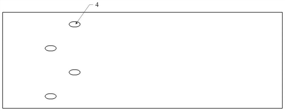
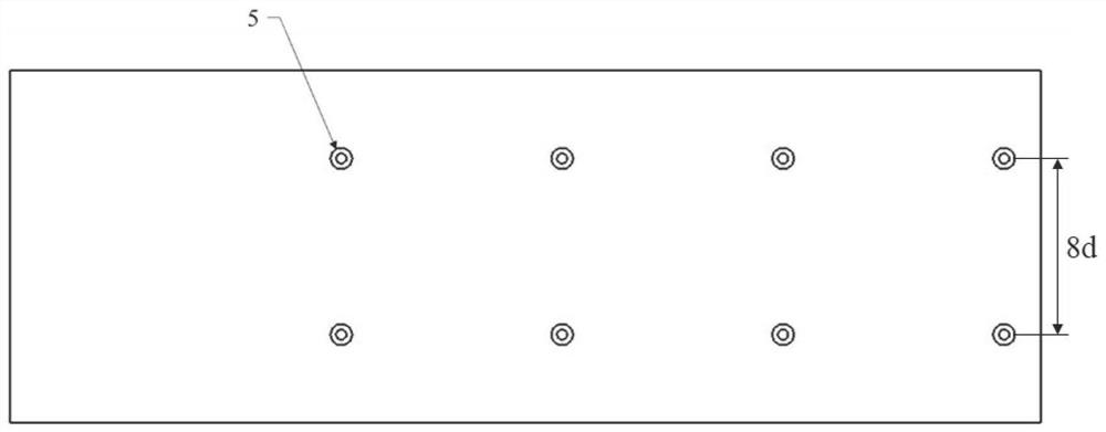
[0043] see figure 1 , the array heat exchange structure in this example is a round platform plus a cylindrical convex structure 2, located on the impact target plate 1, the bottom surface in contact with the impact target surface has a diameter of 3 mm, and the other bottom surface has a diameter of 1.5 mm and a height of 1.25 mm. The inclination angle of the wall is 45°, and the impact distance is 6mm. see figure 2 , the raised structure array is arranged on one side of the impacting target plate, the spacing in the flow direction is 30 mm, and the spacing in the span direction is 24 mm. see image 3 , the gas film hole 4 is located on the other side of the impact target plate, the hole diameter is 2.8mm, the angle between the gas film hole axis and the horizontal plane is 30°, the flow direction spacing is 12mm, the span direction spacing...


PUM

PropertyMeasurementUnit
Axial heightaaaaaaaaaa
Angle of incidenceaaaaaaaaaa

Abstract

The invention discloses an array impact structure based on a circular truncated cone and cylindrical protrusion, and belongs to the field of engine turbines. The array impact structure comprises an air inlet cavity, an impact plate and an impact target plate, and an array circular truncated cone and cylindrical protrusion and a plurality of air film holes which are arranged on the impact target plate; the circular truncated cone and cylindrical protrusion and impact holes in the impact plate are coaxially and oppositely arranged; the plurality of air film holes are formed in the downstream of the array circular truncated cone and cylindrical protrusion located on the impact target plate along the flow direction; the circular truncated cone and cylindrical protrusion comprises a circular truncated cone and a cylinder; the large end of the circular truncated cone serves as a bottom surface and is fixed to the impact target plate in parallel; and the cylinder is coaxially fixed to the small end face, located above, of the circular truncated cone. Compared with cylindrical protrusion target plate impact cooling, the array impact structure based on the circular truncated cone and cylindrical protrusion disclosed by the invention has the advantages that: the heat exchange of the target surface can be increased to a certain extent; the flow loss is reduced; and the area of a region with stronger heat exchange on the target surface is increased.

Description

technical field [0001] The invention belongs to the field of engine turbines, and in particular relates to an array impact structure based on a circular platform plus a cylindrical protrusion. Background technique [0002] With the continuous development of aero-engine technology, the requirements for the thrust-to-weight ratio are getting higher and higher, which requires a higher temperature before the turbine. At present, the temperature before the turbine is much higher than the melting point of the turbine material, which poses a challenge to the cooling of the turbine. . Now a comprehensive protective cooling scheme consisting of internal cooling, external cooling and surface thermal barrier coating has basically been formed. Among them, impingement cooling is one of the cooling structures with the strongest heat transfer effect in internal cooling. [0003] In impingement cooling, the airflow impacts the target surface through the impact hole, absorbing the heat abso...

Claims


Application Information

Patent Timeline
IPC IPC(8): F01D25/12
CPCF01D25/12
Inventor 刘存良师晴晴黄维娜李洁博郭涛许卫疆
Owner NORTHWESTERN POLYTECHNICAL UNIV
Why Eureka
Try Eureka