


Quick Research
Generate reliable direction feasibility study reports for your R&D in just a few steps.

Technical Q&A
Discover and master advanced knowledge NOW. Basics, ideas, possibilities, all at once.

Find Solutions
As an expert in R&D theories, this can generate solutions to your technical problems instantly.

Evaluate Feasibility
Analyze your overall solution with one click, know your potential R&D risks in advance.

Monitor Landscape
Get weekly tech updates, stay abreast of the latest tech innovations and key insights.
Reinforced concrete pipe culvert dredging method
A technology of reinforced concrete and pipe culverts, which is applied in the direction of separation methods, chemical instruments and methods, earth movers/excavators, etc., and can solve problems such as inconvenient dredging of pipes and culverts
- Summary
- Abstract
- Description
- Claims
- Application Information
AI Technical Summary
Problems solved by technology
Method used
Image


Examples
Embodiment 1
[0043] A kind of reinforced concrete pipe culvert dredging method, such as Figure 7 As shown, it includes the following steps:
[0044] S1. The upstream end of the pipe culvert to be dredged is blocked, and the upstream flowing water is introduced into the downstream of the pipe culvert to be dredged through a temporary pipeline;
[0045] S2. Add one or more of the following materials to the inside of the pipe culvert to be dredged: sludge curing agent, sand, soil;
[0046] S3. Use a stirring device to stir and mix the materials added in S2 with the sludge evenly, and stir the sludge to a state close to a solid state that can be excavated and loaded;
[0047] S4. Using an excavator to excavate the mixed silt stirred in S3, and dump the excavated silt into the loading box of the silt loading vehicle;
[0048] S5. After the silt excavation is completed, the blockage of the upstream section is released, and the temporary pipeline is removed at the same time;
[0049] S6. Acco...
Embodiment 2
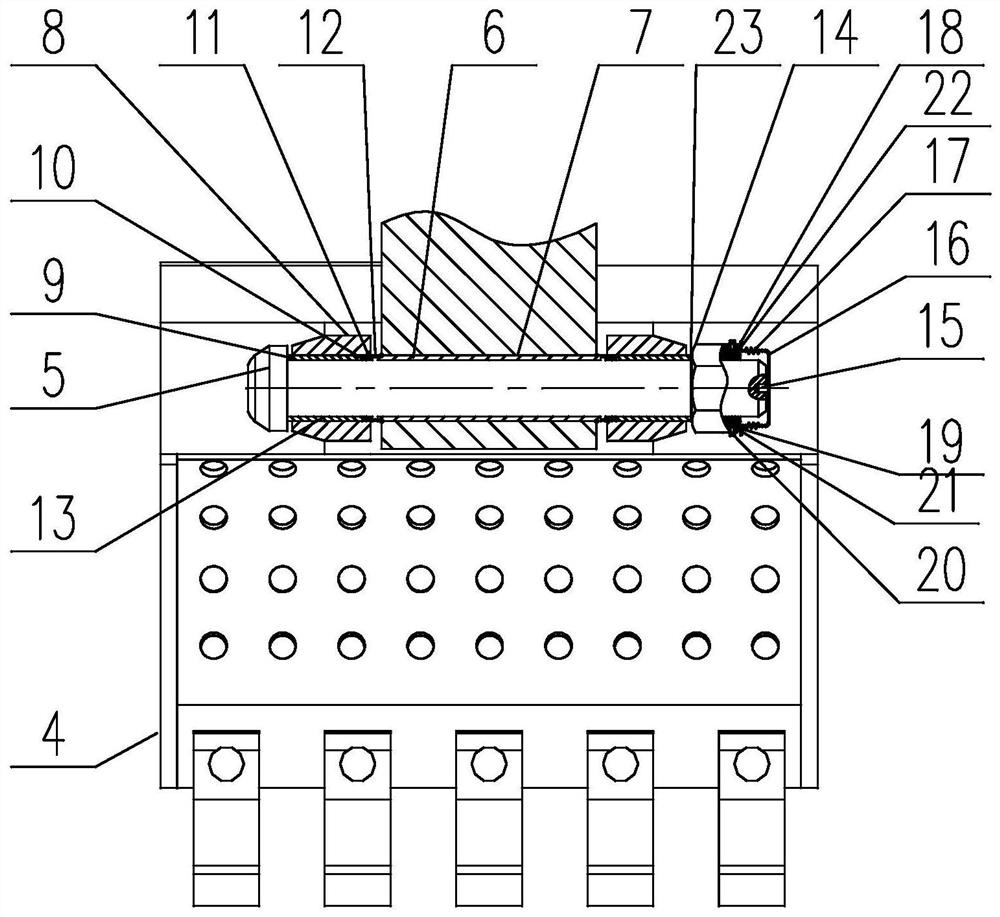
[0052] Such as Figure 1 to Figure 6As shown, the excavator 1 includes a body 2, a mechanical arm 3 installed on the rotating platform of the body 2, and a bucket 4 installed at the end of the mechanical arm 3 through a pin assembly. The pin assembly includes a pin 5, a main The bushing 6, the nut 14 and the ear plate assembly, the main pin hole 7 is arranged on the mechanical arm 3, and the ear plate assembly includes the ear plate 8 and the side bushes 9 coaxial with each other, the inner connecting ring 10, the rolling bearing 11 and the outer The connecting ring 12, the ear plate 8 is installed on the top of the bucket 4, and a side pin hole 13 is arranged on it, the side bushing 9 is spline-fitted with the side pin hole 13, and one end thereof is connected to the rolling bearing 11 through the inner connecting ring 10 The inner ring abuts, the main bush 6 is splined with the kingpin hole 7, and the main bush 6 is fixed on the mechanical arm 3, and one end thereof abuts ag...
Embodiment 3
[0059] This embodiment is based on Embodiment 2 to further illustrate the implementation of the present invention.
[0060] When the excavating device excavates the silt, its surface will be contaminated with dirt, which will damage the thread between the nut and the pin shaft, which is not conducive to the disassembly of the nut later, so if image 3 and Figure 5 As shown, a protective assembly is provided at the end of the pin shaft 5 away from the head of the pin shaft 5, and an annular groove 21 whose axis coincides with it is provided at the end of the nut 14 away from the head of the pin shaft 5;
[0061] The protective assembly includes a bolt 20, a sealing ring 19, a screw rod 15, a positioning cylinder 16, a bellows 17, and an insertion cylinder 18 connected coaxially in sequence. One end of the positioning cylinder 16 is a closed end, and the other end is toward the nut 14. One point of the screw rod 15 is inserted into the inner hole of the positioning cylinder 16...
PUM
 Abstract
Description
Claims
Application Information
 - R&D Engineer
- R&D Manager
- IP Professional
- Industry Leading Data Capabilities
- Powerful AI technology
- Patent DNA Extraction
Browse by: Latest US Patents, China's latest patents, Technical Efficacy Thesaurus, Application Domain, Technology Topic, Popular Technical Reports.
© 2024 PatSnap. All rights reserved.Legal|Privacy policy|Modern Slavery Act Transparency Statement|Sitemap|About US| Contact US: help@patsnap.com