
Melting device for glass fiber production

A melting device and glass fiber technology, applied in glass furnace equipment, glass manufacturing equipment, feeding of melting furnaces, etc., can solve problems such as damage to the respiratory system of workers, pollution of the natural environment, and low efficiency of defoaming

Active Publication Date: 2021-09-10
SHANDONG FIBERGLASS GRP
View PDF7 Cites 1 Cited by
  • Summary
  • Abstract
  • Description
  • Claims
  • Application Information

AI Technical Summary

Problems solved by technology

[0004] Most of the existing melting devices use open feeding. When continuously adding raw materials to the melting device, a large amount of volatile gas generated during the high-temperature melting process overflows from the opening, causing the volatile gas to enter the working environment. The respiratory system of the staff causes irreversible damage; in addition, the clarification tank in the existing melting device is naturally static to clarify and defoam, the defoaming efficiency is low and the defoaming effect is poor, and a large amount of clarifying agent is often required to assist clarification and defoaming. And a large number of clarifiers will cause pollution to the natural environment

Method used


Image

  • Melting device for glass fiber production
  • Melting device for glass fiber production
  • Melting device for glass fiber production

Examples


Embodiment

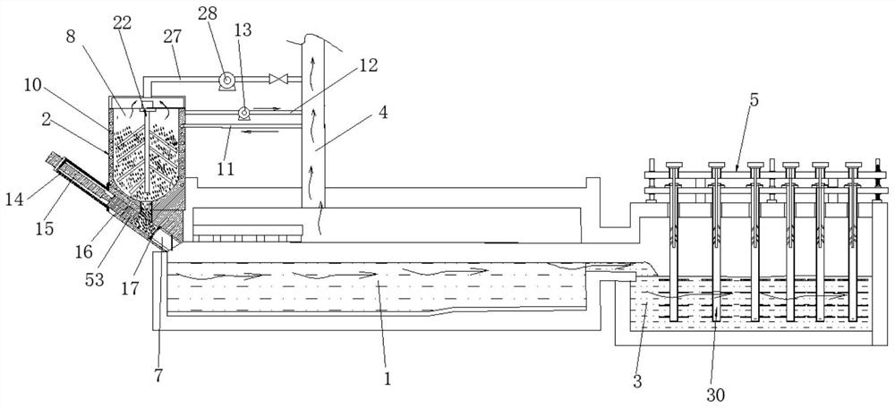
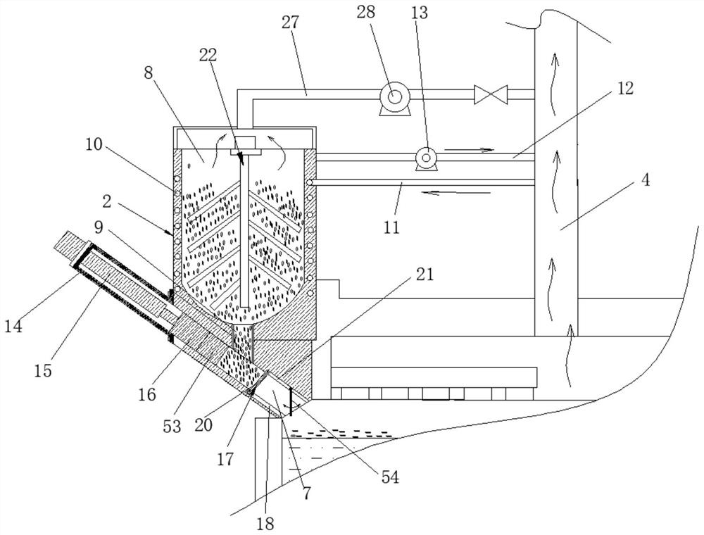
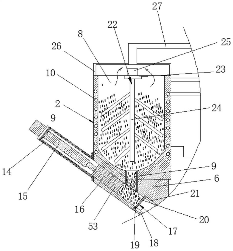
[0034] Example: such as figure 1 , figure 2 , image 3 , Figure 4 , Figure 5 , Image 6 , Figure 7 As shown, a melting device for glass fiber production in the present invention includes a channel-type melting pool 1, and is characterized in that the upstream end of the melting pool 1 is a melting zone, and the port at the upstream end is provided with a closed feeding mechanism 2. The downstream end of the melting pool 1 is provided with a melting zone, the final end of the melting pool 1 is provided with a clarification tank 3, and the top of the melting pool 1 is provided with a smoke exhaust pipe 4; A vibration defoaming mechanism 5 is provided; the closed feeding mechanism 2 includes a sealing block 6 arranged at the port of the upstream end, and the sealing block 6 is provided with a feeding chamber that is inclined downward and communicates with the melting pool 1 7. The side wall of the melting pool 1 is provided with a storage funnel 8, and the bottom of the...


PUM


Abstract

The invention discloses a melting device for glass fiber production. The melting device comprises a channel-type melting tank. The upstream end of the melting tank is a melting zone, and a closed feeding mechanism is arranged at the port of the upstream end. The downstream end of the melting tank is provided with a melting-down zone, the tail end of the melting tank is provided with a clarification tank, and a smoke exhaust pipeline is arranged at the top of the melting tank. and a vibration defoaming mechanism is arranged in the clarification tank. According to the invention, a large amount of volatile gas generated by high-temperature melting is effectively prevented from overflowing from a discharge port, so that the volatile gas is prevented from entering a working environment to cause irreversible damage to the respiratory system of a worker; and through vibration bubble removal, the bubble content of a molten glass solution is reduced, the quality of glass fibers is improved, the use amount of a clarifying agent is reduced, and the pollution to the nature is reduced.

Description

technical field [0001] The invention relates to the technical field of glass fiber production, in particular to a melting device for glass fiber production. Background technique [0002] Glass fiber is an inorganic non-metallic material with excellent performance. There are many kinds. Its advantages are good insulation, strong heat resistance, good corrosion resistance and high mechanical strength. It is made of glass balls or waste glass through high-temperature melting, wire drawing, winding, weaving and other processes. The diameter of its single filament is several microns to more than 20 microns, which is equivalent to 1 of a hair. / 20-1 / 5, each bundle of fiber precursors is composed of hundreds or even thousands of monofilaments, glass fibers are usually used as reinforcing materials in composite materials, electrical insulation materials and thermal insulation materials, circuit substrates and other national economies each field. [0003] Among them, high-strength ...

Claims


Application Information

Patent Timeline
Patent Type & Authority Applications(China)
IPC IPC(8): C03B37/022C03B3/00C03B5/187
CPCC03B37/022C03B3/00C03B5/187
Inventor 崔宝山高贵江解玉琴
Owner SHANDONG FIBERGLASS GRP
Learn More