Shipborne underwater target positioning operation device

A technology for underwater target and positioning operation, applied in the direction of ship hull, ship parts, ship construction, etc., can solve the problems of being easily attached by parasites, easily disturbed by target positioning operation device, and garbage package of detection device.

Pending Publication Date: 2021-09-10
ZHEJIANG OCEAN UNIV
View PDF9 Cites 3 Cited by
  • Summary
  • Abstract
  • Description
  • Claims
  • Application Information

AI Technical Summary

Problems solved by technology

[0003] The existing ship-borne underwater target positioning operation device is susceptible to interference. Some existing ship-based underwater target positioning operating devices place the detection device underwater and transmit signals in the same direction through the detection device. When encountering an object, the signal Reflected back, so that the whole device can detect the situation ahead, but there is a certain amount of garbage in the water, which moves with the ocean current, and then it is easy to make the detection device without the cleaning device wrapped in garbage, and then it is easy to cause the detection signal of the whole device to be affected when it is detecting. Interference, and long-term exposure to the outside is easy to be attached by parasites, which has brought certain adverse effects on people's use. Therefore, we propose a ship-borne underwater target positioning operation device

Method used


Image

  • Shipborne underwater target positioning operation device
  • Shipborne underwater target positioning operation device
  • Shipborne underwater target positioning operation device

Examples


specific Embodiment 1

[0029] This embodiment is a ship-borne underwater target positioning operation device.

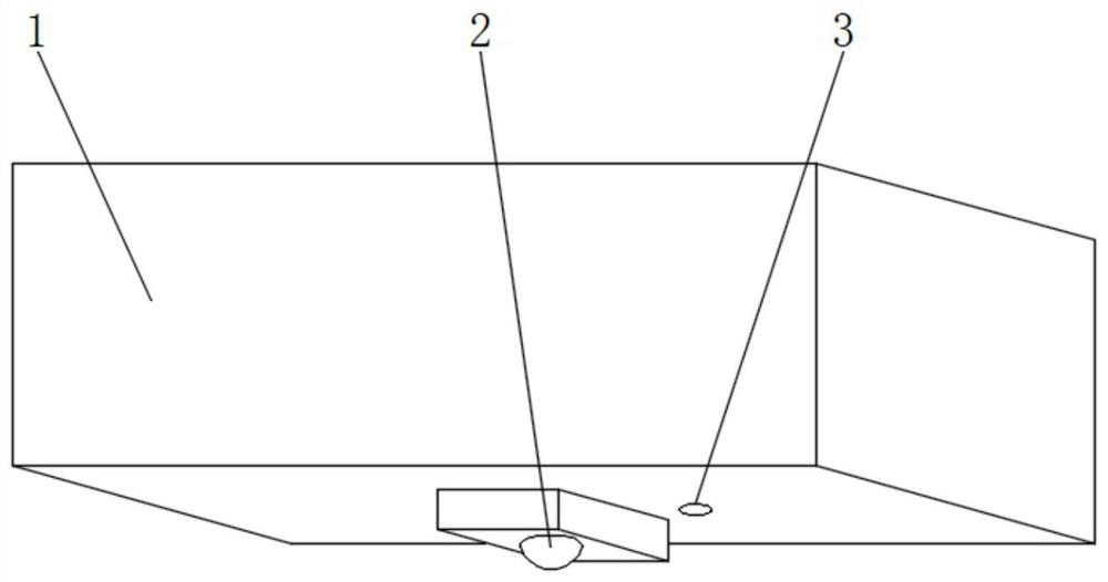
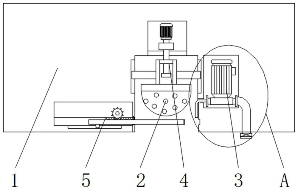
[0030] Such as Figure 1-5 As shown, including the ship bottom plate 1, the lower outer surface of the ship bottom plate 1 is provided with a sonar detection device 2, and a lifting mechanism 4 is arranged between the sonar detection device 2 and the ship bottom plate 1, and the upper end outer surface of the sonar detection device 2 passes through the lifting mechanism 4 It is fixedly connected with the bottom plate 1 of the ship, and one side of the sonar detection device 2 is provided with a sealing mechanism 5 , and the other side of the sonar detection device 2 is provided with a drainage mechanism 3 .

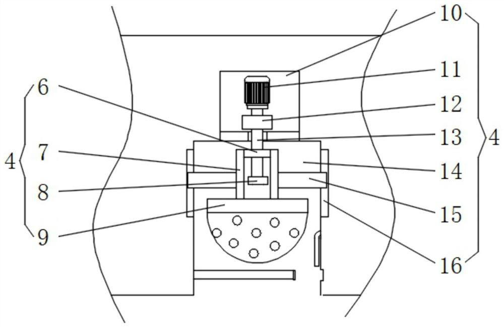
[0031]The lifting mechanism 4 includes a moving rod 6, a support rod 7, a limit block 8, a mounting plate 9, a first mounting cavity 10, a positive and negative motor 11, a first reduction box 12, a screw rod 13, a movable cavity 14, and a first slider 15 With the first chute 16, and...

specific Embodiment 2

[0034] This embodiment is an embodiment of the lifting mechanism 4 in the ship-borne underwater target positioning operation device.

[0035] Such as figure 1 , 2 , 3, a lifting mechanism 4 for a ship-borne target positioning operation device in water, the lifting mechanism 4 includes a moving rod 6, a support rod 7, a limit block 8, a mounting plate 9, a first mounting cavity 10, a positive and negative motor 11. The first reduction box 12, the screw 13, the movable cavity 14, the first slider 15 and the first chute 16, and the movable cavity 14 is set on the lower outer surface of the bottom plate 1, and the first installation cavity 10 is set on the bottom plate 1, and the first installation chamber 10 is located at the upper end of the activity chamber 14, the first chute 16 is opened on the outer surface of both sides of the activity chamber 14, the positive and negative motor 11 is fixedly installed inside the first installation chamber 10, the first The reduction box ...

specific Embodiment 3

[0037] This embodiment is an embodiment of the sealing mechanism 5 in the ship-borne underwater target positioning operation device.

[0038] Such as figure 1 , 2 , shown in 4, a kind of sealing mechanism 5 that ship-borne underwater target positioning operation device is used, sealing mechanism 5 comprises second installation chamber 17, installation block 18, second chute 19, second slider 20, rotating shaft 21, tooth Dental plate 22, gear 23, one-way valve outlet hole 24, slideway 25, baffle plate 26, sealing washer 27, draw-in groove 28, waterproof motor 29 and second reduction box 31, and slideway 25 is opened in activity cavity 14- The lower part of the side inner wall, the draw-in groove 28 is provided in the lower part of the inner wall of the other side of the movable chamber 14, the second installation chamber 17 is opened on one side of the slideway 25, and the installation block 18 is fixedly installed in the inside of the second installation chamber 17, and is se...


PUM


Abstract

A shipborne underwater target positioning operation device disclosed by the present invention comprises a ship bottom plate, a sonar detection device is arranged on the outer surface of the lower end of the ship bottom plate, a lifting mechanism is arranged between the sonar detection device and the ship bottom plate, and the outer surface of the upper end of the sonar detection device is fixedly connected with the ship bottom plate through the lifting mechanism. And a sealing mechanism is arranged on one side of the sonar detection device. According to the shipborne underwater target positioning operation device, the lifting mechanism is arranged, a screw is driven to rotate through operation of a forward and reverse motor, the screw rotates to enable a moving rod to move in the direction of the screw, the moving rod drives a mounting plate to move upwards through a supporting rod, therefore, the sonar detection device is received into a movable cavity, the sonar detection device is prevented from being soaked in seawater for a long time in cooperation with the sealing mechanism and the drainage mechanism, the adhesion rate of garbage or aquatic creatures in water is reduced, and a better use prospect is brought.

Description

technical field [0001] The invention relates to the technical field of ship positioning, in particular to a ship-borne underwater target positioning operation device. Background technique [0002] 70% of the earth's surface is water, and ships allow us to move freely in the water to transport goods. At the same time, the sea area is also unknown. People use the detection devices on the ships to locate and operate the targets in the water, not only to explore The unknown underwater world can also prevent the ship from touching reefs and other objects at the same time, improving the stability of the ship. [0003] The existing ship-borne underwater target positioning operation device is susceptible to interference. Some existing ship-based underwater target positioning operating devices place the detection device underwater and transmit signals in the same direction through the detection device. When encountering an object, the signal Reflected back, so that the whole device ...

Claims


Application Information

Patent Timeline
Patent Type & Authority Applications(China)
IPC IPC(8): B63B17/00B63B13/00F16J15/06
CPCB63B17/00B63B13/00F16J15/06B63B2017/0054
Inventor 刘娟意
Owner ZHEJIANG OCEAN UNIV
Why Eureka
Try Eureka