Locking stress component of tool quick-changing device and treatment process thereof

A technology of force-bearing parts and tools, which is applied in the field of tool quick-change device locking force-bearing parts and its processing technology, which can solve the problems of easy oxidation and rust, low hardness, inconvenient disassembly and assembly, etc.

Pending Publication Date: 2021-09-10
郑州领航机器人有限公司
View PDF9 Cites 0 Cited by
  • Summary
  • Abstract
  • Description
  • Claims
  • Application Information

AI Technical Summary

Problems solved by technology

[0003] In order to solve the problem in the prior art that the locking parts of the upper connecting plate and the lower connecting plate are inconvenient to disassemble, and the hardness is low, easy to oxidize and rust, which seriously shortens the service life of the locking parts, a tool quick changer is invented. Locking force-bearing parts of the device and its treatment process

Method used


Image

  • Locking stress component of tool quick-changing device and treatment process thereof
  • Locking stress component of tool quick-changing device and treatment process thereof
  • Locking stress component of tool quick-changing device and treatment process thereof

Examples


Embodiment Construction

[0026] The technical solutions of the various embodiments of the present invention will be clearly and completely described below in conjunction with the accompanying drawings. Apparently, the described embodiments are only some of the embodiments of the present invention, not all of them. Based on the embodiments of the present invention, all other embodiments obtained by persons of ordinary skill in the art without creative work belong to the protection scope of the present invention. In the description of the present invention, it should be noted that, The orientation or positional relationship indicated by the terms "center", "upper", "lower", "left", "right", "vertical", "horizontal", "inner", "outer" and the like are based on the The orientation or positional relationship is only for the convenience of describing the present invention and simplifying the description, but does not indicate or imply that the device or element referred to must have a specific orientation, be...


PUM


Abstract

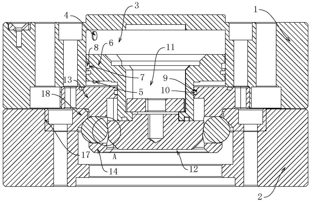
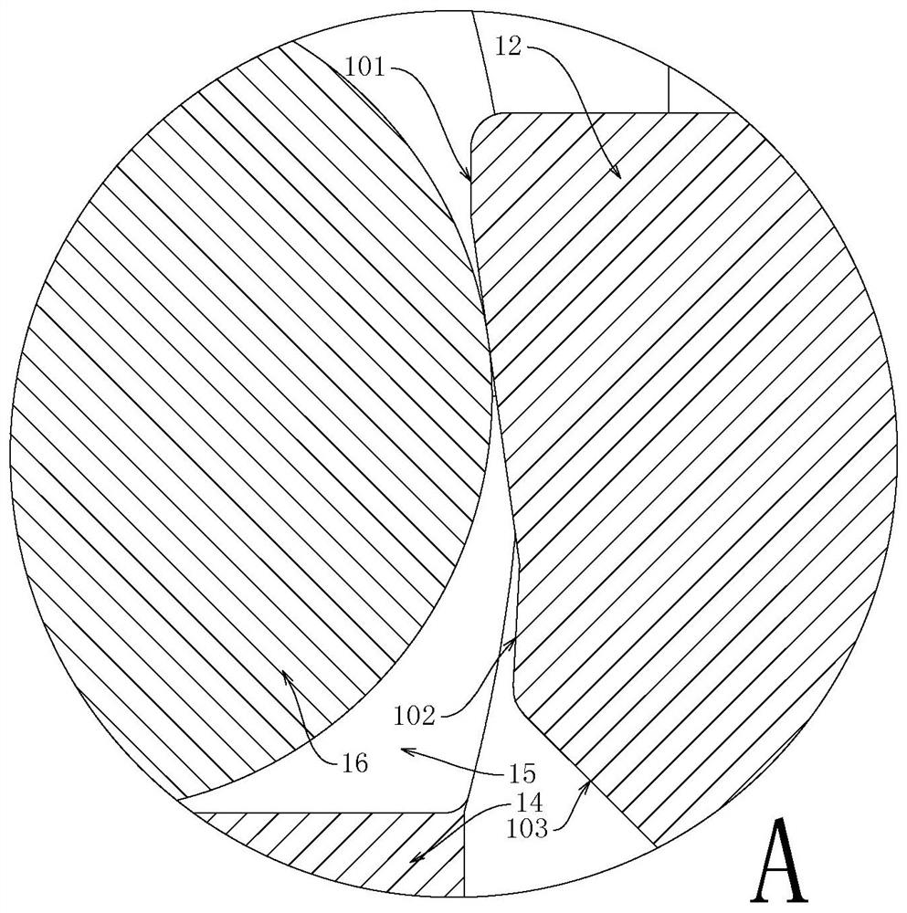
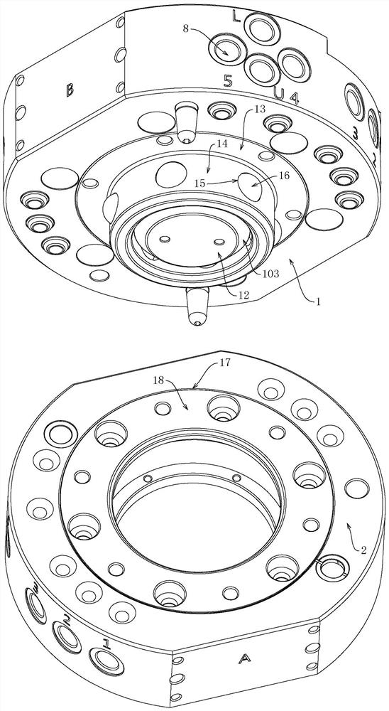
The invention relates to the technical field of quick-change devices, in particular to a locking stress component of a tool quick-changing device and a treatment process thereof. The locking stress component comprises a piston disc, a piston rod, a locking cam, a flange disc, a locking ring, a locking ball and a locking seat, wherein the locking stress components are all made of martensitic stainless steel materials, the locking stress components are arranged on an upper connecting disc, the piston disc is movably connected into an inner cavity formed in the upper connecting disc, the locking cam is fixed to the piston disc through the piston rod, the locking ring is fixed to an opening of the inner cavity through the flange plate, a plurality of locking balls are movably connected to the locking ring, a lower connecting disc matched with the upper connecting disc is arranged below the upper connecting disc, the locking seat is fixed to the axis of the lower connecting disc, and a structure that a locking cam presses a locking ball to be clamped to the locking seat is formed. The quick-changing device realizes quick locking and replacement, and is high in hardness and good in antirust effect; and the device has a wide application prospect in the technical field of quick-changing devices.

Description

technical field [0001] The invention relates to the technical field of quick-change devices, in particular to a tool quick-change device for locking force-bearing parts and its processing technology. Background technique [0002] The quick change device for robots, also known as tool quick change disc, gun change disc, etc., is a flexible connection tool used in the industrial robot industry for end effectors. The quick change device is composed of an upper connection plate and a lower connection plate. Usually, one upper connection plate is fixed on the mechanical arm, and end effectors with different functions are fixed on multiple lower connection plates. When in use, the upper connection plate is connected to the lower connection plate. The quick change of the disk, the replacement of the mechanical arm to operate different equipment. In the prior art, the locking parts of the upper connection plate and the lower connection plate are inconvenient to disassemble, and the...

Claims


Application Information

Patent Timeline
Patent Type & Authority Applications(China)
IPC IPC(8): B25J15/04B23P15/00
CPCB25J15/04B23P15/00
Inventor 陈志峰陈浩杰赵杰
Owner 郑州领航机器人有限公司
Why Eureka
Try Eureka