
Weld joint reinforcement automatic milling device and path generation method and using method

A technology of automatic milling and weld reinforcement, applied in the direction of manipulators, program-controlled manipulators, manufacturing tools, etc., can solve problems such as difficulties

Active Publication Date: 2021-09-10
NANJING INST OF TECH
View PDF5 Cites 0 Cited by
  • Summary
  • Abstract
  • Description
  • Claims
  • Application Information

AI Technical Summary

Problems solved by technology

Under the harsh conditions where the height of the base metal on both sides of the weld is inconsistent due to the wrong side of the assembly, or the constraints and materials are different, resulting in inconsistent welding deformation of the base metal on both sides of the weld, it becomes more difficult to automatically remove the weld reinforcement by milling, even if advanced It is also difficult for laser sensors to avoid accidental damage to the base metal during milling under harsh conditions

Method used


Image

  • Weld joint reinforcement automatic milling device and path generation method and using method
  • Weld joint reinforcement automatic milling device and path generation method and using method
  • Weld joint reinforcement automatic milling device and path generation method and using method

Examples


specific example 1

[0043] The material is 16Mn, the shape is plate-like, and the workpiece 21 to be processed is 1m long, 0.5m wide, and 10mm thick. , the to-be-milled weld 23 is a linear weld with a length of 1 m. Such as Image 6 As shown, the surface of the workpiece 21 to be processed that needs to have weld reinforcement removed is the pseudo-milling surface 24 . The width of the fusion width 25 of the to-be-milled weld on the to-be-milled surface is 13-15mm, and the height of the to-be-milled weld's reinforcement 26 on the to-be-milled surface is 4-6mm, which needs to be removed after welding.

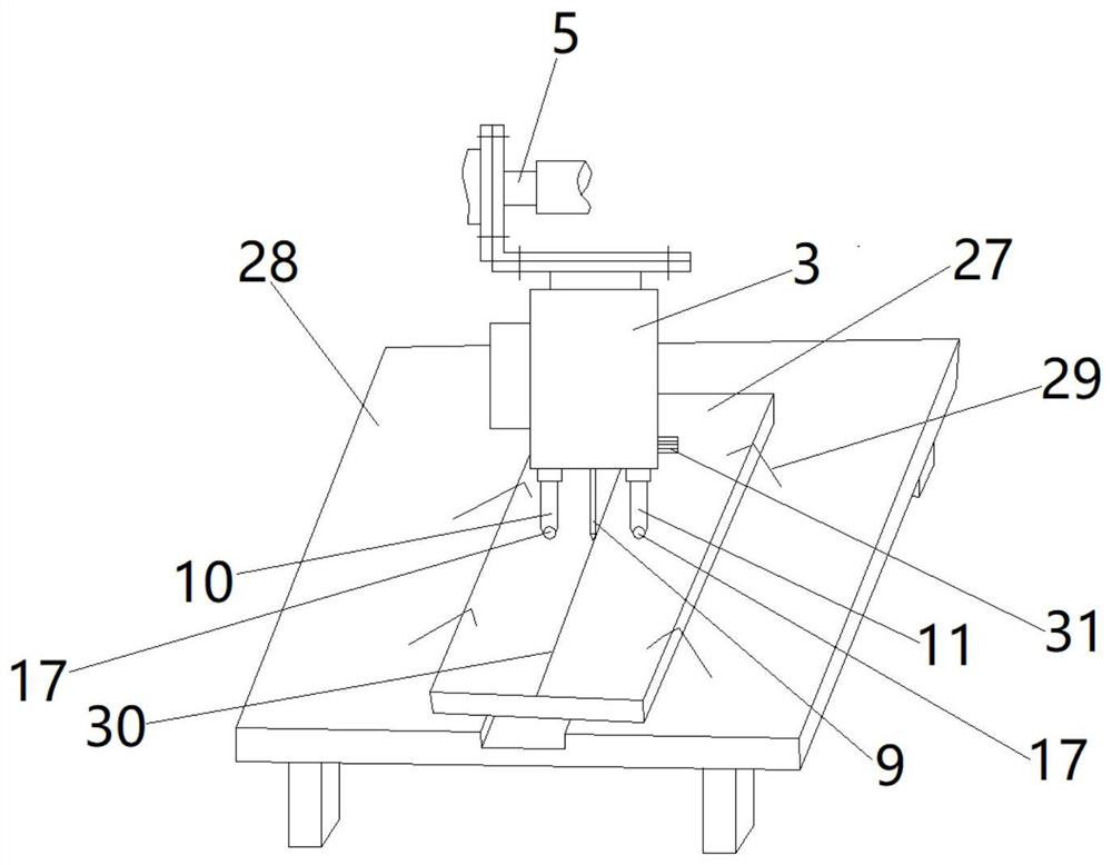
[0044] First teach robot 1, such as image 3 As shown, before teaching, it is necessary to install the teaching thimble 9 on the milling path pick-up module 3, and prepare a standard workpiece 27. The standard workpiece 27 adopts a base material 22 of the same specification, that is, a 1m long, 0.25m wide, and 10mm thick steel plate. Place the standard workpiece 27 on the console 28, install an...

specific example 2

[0051] The material is Q235, the shape is semi-tubular, and the size specification is 10m in length, 0.25m in radius, and 12mm in thickness. The proposed milling weld is a semi-circular weld with a length of 0.785m. The concave surface of the processed workpiece is the pseudo-milling surface. The width of the fusion width of the to-be-milled weld on the to-be-milled surface is 15-17mm, and the height of the reinforcement of the to-be-milled weld to be located on the to-be-milled surface is 5-7mm, which needs to be removed after welding.

[0052] In this example: (1) The standard workpiece adopts a base material of the same specification, that is, a semi-tubular base material with a length of 5m, a radius of 0.25m, and a thickness of 12mm. (2) Special fixtures are required for positioning and clamping Standard workpieces and processed workpieces. Except that the above two places are different, other places are all the same as the method adopted in concrete example 1.

specific example 3

[0054] The material is 6061 aluminum alloy, the shape is wavy, and the size specification is 1m in length, 0.8m in width, and 6mm in thickness. It is tailor-welded along the length direction, and the to-be-milled weld is a wavy weld, which is 1.5m long after straightening. The surface on which the weld reinforcement needs to be removed on the processed workpiece is the pseudo-milling surface. The width of the fusion width of the to-be-milled weld on the to-be-milled surface is 10-13mm, and the height of the reinforcement of the to-be-milled weld to be located on the to-be-milled surface is 3-4mm, which needs to be removed after welding.

[0055] In this example: (1) The standard workpiece adopts a base material of the same specification, that is, a wavy base material with a length of 1m, a width of 0.4m, and a thickness of 6mm. (2) Special fixtures are required to position and clamp the standard workpiece and Workpiece to be processed. Except that the above two places are di...


PUM


Abstract

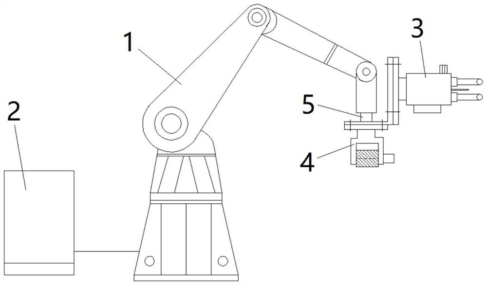
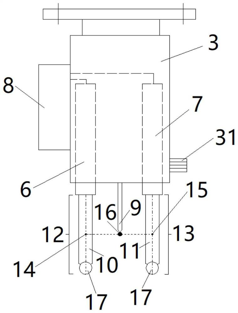
The invention discloses a weld joint reinforcement automatic milling device and path generation method and a using method. The weld joint reinforcement automatic milling device comprises a robot, the wrist of the robot is connected with a milling path pickup module and a milling module, the milling path pickup module comprises a teaching ejector pin and multiple displacement sensors, each displacement sensor is provided with a sliding measuring rod, and rolling wheels are arranged at the ends of the sliding measuring rods. According to the weld joint reinforcement automatic milling device and path generation method and the using method, the weld joint reinforcement automatic milling path is generated by taking the surfaces of base materials near the two sides of a weld joint as references to realize automatic milling of the weld joint reinforcement, so that the machined surface of the weld joint keeps consistent with the surfaces of the base materials near the weld joint, the aim of accurately removing the weld joint reinforcement is achieved under the condition that the base materials are not accidentally damaged, and the weld joint reinforcement automatic milling device and path generation method and the using method are particularly suitable for accurately and efficiently removing the weld joint reinforcement under the harsh conditions that welding deformation is large, a joint has misalignment, or deformation of the base materials on the two sides of the weld joint is inconsistent.

Description

technical field [0001] The invention relates to an automatic milling device, a path generation method and a use method, in particular to an automatic milling device for weld reinforcement, a path generation method and a use method. Background technique [0002] Removing the weld reinforcement after welding not only makes the appearance of the weld consistent with the base metal, but also eliminates the source of local stress in the welded joint, and also avoids the possibility of premature failure of the welded joint due to welding defects that may exist in the weld reinforcement question. Therefore, many welded structures need to remove the weld reinforcement after welding. At present, manual grinding is often used to remove the weld reinforcement, and the efficiency of manual grinding is low, especially for high-hardness materials. The grinding efficiency is lower, and the labor intensity of the grinding workers The large amount of dust and high-decibel noise generated du...

Claims


Application Information

Patent Timeline
Patent Type & Authority Applications(China)
IPC IPC(8): B25J11/00B25J9/16B25J9/00
CPCB25J11/005B25J9/1664B25J9/0081
Inventor 杨宗辉李晓泉王章忠成家林初雅杰张旭
Owner NANJING INST OF TECH
Learn More