Differential pressure gauge machining equipment and using method thereof

A processing equipment, differential pressure gauge technology, applied in metal processing equipment, metal processing, mechanical equipment and other directions, can solve the problems of incomplete assembly, unstable clamping, affecting assembly efficiency and the quality of the whole machine.

Active Publication Date: 2021-09-10
安徽润仪自动化仪表有限公司
View PDF7 Cites 2 Cited by
  • Summary
  • Abstract
  • Description
  • Claims
  • Application Information

AI Technical Summary

Problems solved by technology

[0006] Aiming at the deficiencies of the prior art, the present invention provides a differential pressure gauge processing equipment and its use method, which solves the problem that the existing double bellows structure differential pressure gauge cannot form a production line assembly when as

Method used


Image

  • Differential pressure gauge machining equipment and using method thereof
  • Differential pressure gauge machining equipment and using method thereof
  • Differential pressure gauge machining equipment and using method thereof

Examples


Embodiment

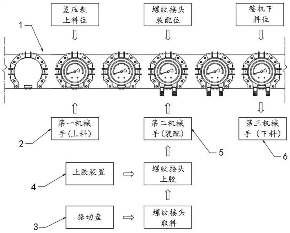
[0047] Such as Figure 1-8 As shown, a differential pressure gauge processing equipment proposed by an embodiment of the present invention, the structure of the differential pressure gauge is as follows Figure 7 As shown, the differential pressure gauge processing equipment includes:

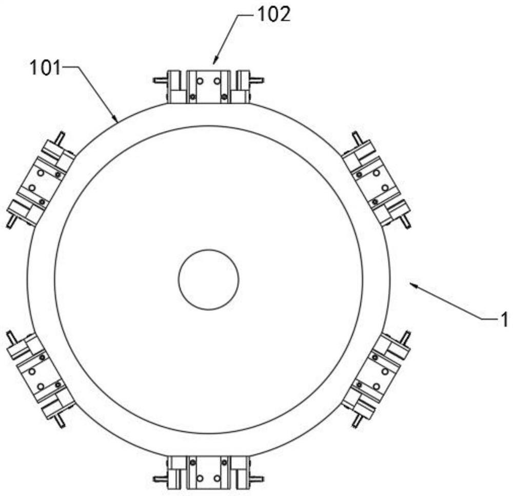
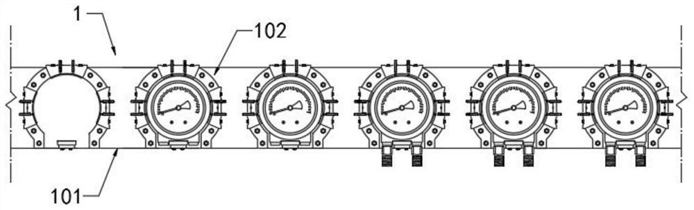
[0048] Rotary disk mechanism 1, such as figure 1 As shown, there are at least three processing stations including a differential pressure gauge upper material level, a threaded joint assembly position, and a complete machine lower material level. A turntable 101 and an actuator that drives the turntable 101 to rotate intermittently (not shown in the figure), Among them, the positions of the upper material level of the differential pressure gauge, the assembly position of the threaded joint and the lower material level of the complete machine are arranged in sequence. The outer edge of the turntable 101 is evenly distributed with positioning mechanisms 102 in the circumferential direction. The ...


PUM


Abstract

The invention belongs to the technical field of differential pressure gauges, and particularly relates to differential pressure gauge machining equipment and a using method thereof. The differential pressure gauge machining equipment comprises a rotating disc mechanism and a rotating disc provided with at least three machining stations including a differential pressure gauge feeding station, a screwed joint assembling station and a whole machine discharging station; and the machining equipment further comprises a first manipulator, a vibration disc, a gluing device, a second manipulator, a third manipulator and a controller. According to the machining equipment, high intelligence of threaded connector assemblies is achieved in a multi-station automatic assembly machining mode, the technical requirement for workers is greatly lowered, the assembly efficiency is improved, the positioning mode of integrating laser positioning and pressure sensing positioning is adopted, a differential pressure gauge completes clamping operation in the state that a mechanical arm presses, the positioning precision and the clamping stability are guaranteed, longitudinal or transverse deviation of the differential pressure gauge is prevented, and meanwhile, the problem that the assembly efficiency and the whole machine quality are affected due to the fact that interfaces are not aligned or the assembly is not thorough when the screwed joints are assembled is solved.

Description

technical field [0001] The invention relates to the technical field of differential pressure gauges, in particular to differential pressure gauge processing equipment and a method for using the same. Background technique [0002] The stainless steel differential pressure gauge is suitable for measuring the differential pressure, flow and other parameters of various liquid (gas) media in the process of chemical industry, chemical brazing, metallurgy, electric power, nuclear power and other industrial sectors. The instrument structure is all made of stainless steel, and the measuring system (double bellows emergency connection parts) and the pressure guiding system (including joints, conduits, etc.) adopt special structures with reasonable design, advanced technology, small size, light weight and good stability. , long service life, novel appearance, strong adaptability and other advantages. There are two connection forms of instrument joints: parallel type (directly connecte...

Claims


Application Information

Patent Timeline
IPC IPC(8): B23P19/06F16B11/00B23P19/00
CPCB23P19/06F16B11/006B23P19/001
Inventor 严同林
Owner 安徽润仪自动化仪表有限公司
Why Eureka
Try Eureka