
Semantic live-action three-dimensional reconstruction method and system of laser fusion multi-view camera

A multi-camera, 3D reconstruction technology, applied in the field of semantic real scene 3D reconstruction of laser fusion multi-camera, can solve the problem that the scene reconstruction model cannot meet the requirements of high precision and high information, achieve rich point cloud density, easy to use Acquiring, high-precision effects

Active Publication Date: 2021-09-07
SHANDONG UNIV
View PDF6 Cites 7 Cited by
  • Summary
  • Abstract
  • Description
  • Claims
  • Application Information

AI Technical Summary

Problems solved by technology

However, the inventor found that the traditional 3D model reconstruction can no longer meet the high-precision and high-information requirements of the scene reconstruction model in real operations

Method used


Image

  • Semantic live-action three-dimensional reconstruction method and system of laser fusion multi-view camera
  • Semantic live-action three-dimensional reconstruction method and system of laser fusion multi-view camera
  • Semantic live-action three-dimensional reconstruction method and system of laser fusion multi-view camera

Examples


Embodiment 1

[0034] Firstly, each sensor such as lidar, multi-eye camera, and IMU (inertial measurement unit) has a fixed relative pose, such as image 3 As shown, then calibrate the sensors to obtain the external parameters between the sensors, and the external parameters between the lidar and the IMU are expressed as The external parameters between the IMU and the i-th camera are expressed as The external parameters between the lidar and the i-th camera are expressed as Calibrate the camera to obtain the internal reference K of the i-th camera i and distortion coefficient (k 1 , k 2 ,p 1 ,p 2 , k 3 ) i . The calibrated sensors form a set of data acquisition system.

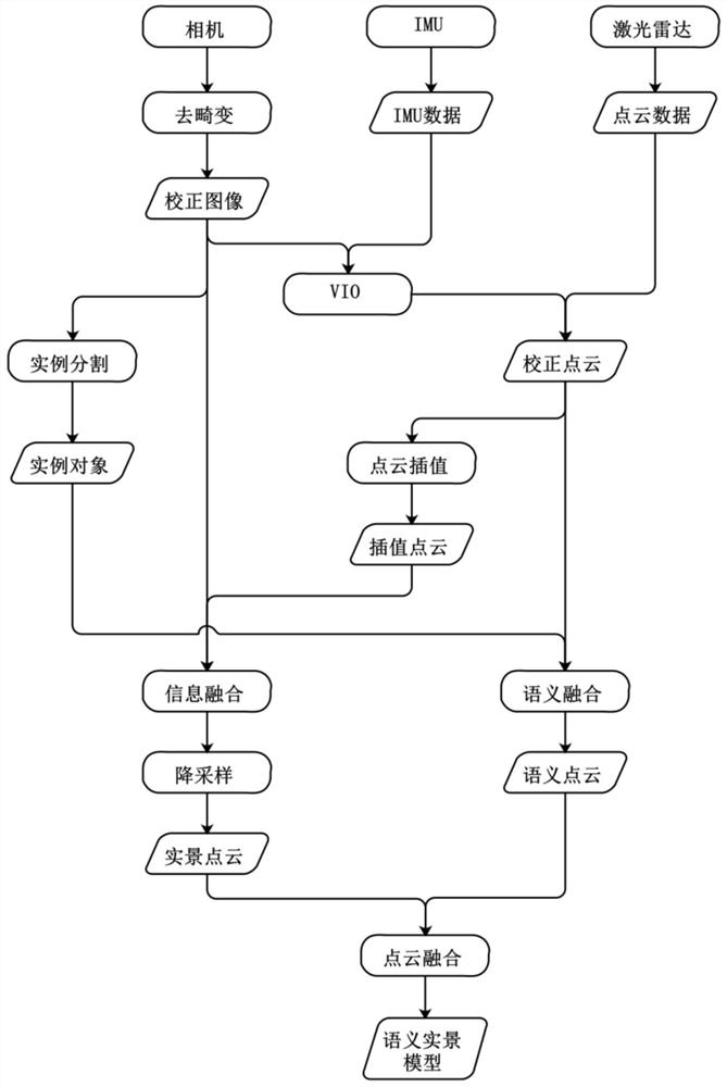
[0035] Such as figure 1 As shown, the present embodiment uses the above-mentioned data acquisition system to provide a semantic real scene three-dimensional reconstruction method of laser fusion multi-eye camera, which specifically includes the following steps:

[0036] Step 1: Acquire multi-camera images and c...

Embodiment 2

[0062] This embodiment provides a semantic real-scene 3D reconstruction system for laser fusion with multi-eye cameras, which specifically includes the following modules:

[0063] Multi-camera image acquisition and correction module, which is used to acquire multi-camera images and correct multi-camera images;

[0064] A laser point cloud data acquisition and correction module, which is used to acquire laser point cloud data and visual inertial odometry data, and align the laser point cloud data with the visual inertial odometer data according to the time stamp to correct the laser point cloud data;

[0065] Real point cloud building module, which is used to interpolate corrected laser point cloud data, obtain dense point cloud and project it to the imaging plane, and then match the pixels of the corrected multi-eye camera image to obtain each frame with RGB The dense point cloud of information is superimposed to obtain the real point cloud;

[0066] The semantic fusion modul...

Embodiment 3

[0069] This embodiment provides a computer-readable storage medium, on which a computer program is stored, and when the program is executed by a processor, the steps in the method for semantic real-scene 3D reconstruction of a laser fusion multi-eye camera as described in the first embodiment are implemented .


PUM


Abstract

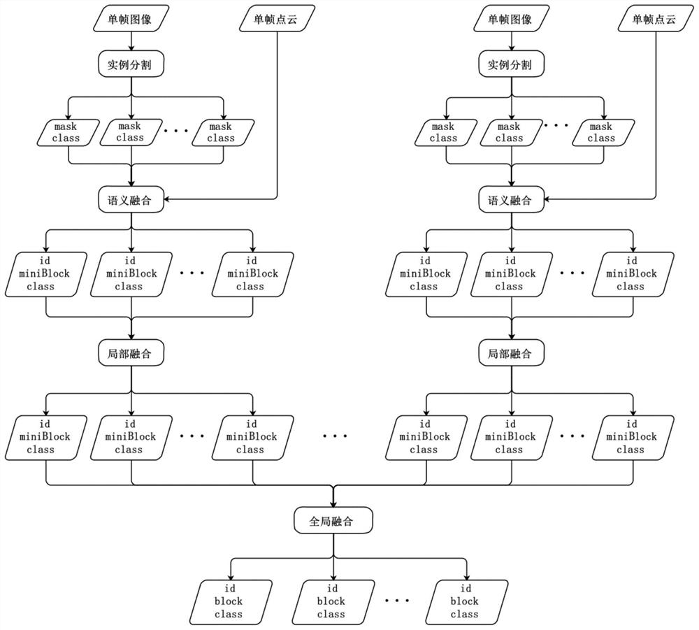
The invention belongs to the technical field of three-dimensional reconstruction of multi-sensor fusion, and provides a semantic live-action three-dimensional reconstruction method and system of a laser fusion multi-view camera. The method comprises the following steps: acquiring a multi-view camera image and correcting the multi-view camera image; acquiring laser point cloud data and visual inertial odometer data, and aligning the laser point cloud data with the visual inertial odometer data according to a timestamp to correct the laser point cloud data; interpolating the corrected laser point cloud data to obtain dense point cloud, projecting the dense point cloud to an imaging plane, matching the dense point cloud with pixels of the corrected multi-view camera image to obtain dense point cloud with RGB information of each frame, and superposing the dense point cloud to obtain real-view point clouds; and obtaining semantic information from the corrected multi-view camera image, matching the semantic information with the corrected point cloud to obtain instance object point cloud, and fusing the instance object point cloud with real scene point cloud to obtain a three-dimensional model for semantic real scene reconstruction.

Description

technical field [0001] The invention belongs to the technical field of three-dimensional reconstruction of multi-sensor fusion, and in particular relates to a semantic real-scene three-dimensional reconstruction method and system of laser fusion multi-eye camera. Background technique [0002] The statements in this section merely provide background information related to the present invention and do not necessarily constitute prior art. [0003] 3D reconstruction is the most important technical means to obtain 3D structural information in the real world, and it is also an important research topic in the fields of photogrammetry, computer vision, and remote sensing mapping. Currently commonly used 3D reconstruction methods mainly use point cloud scanning devices to generate point cloud 3D models, including time-of-flight (TOF) and stereo vision. Stereo vision mainly uses cameras as data acquisition equipment, which has the advantages of low equipment cost and large measureme...

Claims


Application Information

Patent Timeline
Patent Type & Authority Applications(China)
IPC IPC(8): G06T5/00G06T7/11G06T7/521G06T7/80G06T17/00
CPCG06T7/11G06T7/521G06T7/80G06T17/00G06T2207/10028G06T2207/10044G06T2207/30244G06T5/80Y02T10/40
Inventor 皇攀凌欧金顺周军林乐彬赵一凡李留昭
Owner SHANDONG UNIV
Learn More