Damper vibration reduction system for restraining bridge vibration and implementation method
A vibration damping system and damper technology, applied in bridges, bridge parts, bridge construction, etc., can solve the problems of difficult application of damping force and unstable damping effect, and achieve the effect of low cost, ingenious design, and good vibration control.
- Summary
- Abstract
- Description
- Claims
- Application Information
AI Technical Summary
Problems solved by technology
Method used
Image

Examples
specific Embodiment approach 1
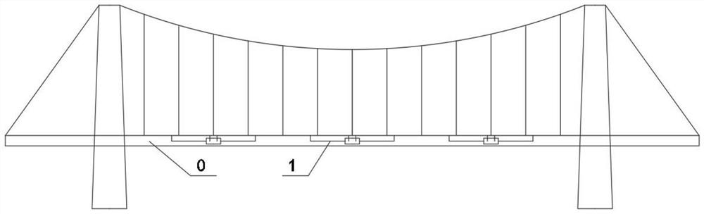
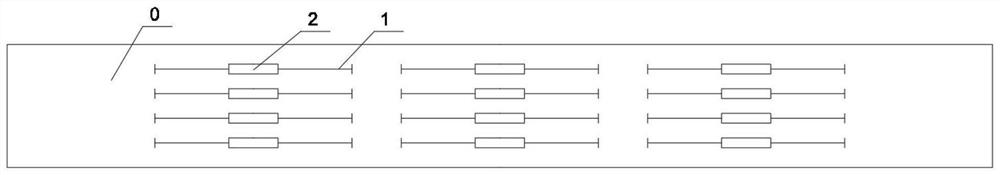
[0036] Specific implementation mode one: combine figure 1 , 2and 4 illustrate this embodiment, a damper damping system for suppressing bridge vibration in this embodiment, including a deformation displacement conversion amplification device 1 and a damper 2, and both ends of the damper 2 are connected by the deformation displacement conversion amplification device 1 and the bridge The main girder 0 establishes a connection. When the bending vibration of the bridge main girder 0 occurs, the deformation displacement conversion amplification device 1 converts the angular displacement generated by the vertical bending vibration into a horizontal displacement difference, and transmits it to the damper 2, and the damper 2 is reversed. The main girder 0 of the bridge is stretched and pulled to suppress the vertical bending vibration of the main girder 0 of the bridge. When the main girder 0 of the bridge vibrates and deforms, the deformation displacement conversion amplification devi...
specific Embodiment approach 2
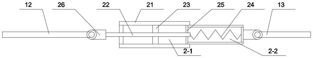
[0037] Specific implementation mode two: combination Figure 1-Figure 5 Describe this embodiment, based on specific embodiment one, a damper vibration reduction system for suppressing bridge vibration in this embodiment, the damper 2 includes an outer shell 21, a piston rod 22, a piston 23, a return spring 24 and a partition Plate 25, the inside of the outer casing 21 is divided into a piston chamber 2-1 and a reset chamber 2-2 by a partition plate 25, and the return spring 24 is arranged in the reset chamber 2-2, and one end of the piston rod 22 runs through the left side of the outer casing 21 and deforms The displacement conversion amplification device 1 establishes a connection through a spherical bearing 26, and the other end of the piston rod 22 passes through a partition plate 25 to establish a connection with a return spring 24. The right side of the outer shell 21 is connected to the deformation displacement conversion amplification device 1 through a spherical bearing...
specific Embodiment approach 3
[0038] Specific implementation mode three: combination Figure 1-Figure 5 Describe this embodiment, based on specific embodiment 1, a damper vibration reduction system for suppressing bridge vibration in this embodiment, the deformation displacement conversion amplification device 1 includes a fixed box 11, a left amplification device 12 and a right amplification device 13 , the fixed box 11 is fixedly installed at the bottom of the bridge girder 0, the left amplifier 12 and the right amplifier 13 are both arranged in the fixed box 11, and one end of the left amplifier 12 passes through the fixed box 11 and the bottom of the bridge girder 0 to establish Connection, the other end of the left amplification device 12 is connected with the piston rod 22 through a spherical bearing 26, one end of the right amplification device 13 passes through the fixed box 11 and establishes a connection with the bottom of the bridge girder 0, and the other end of the right amplification device 13...
PUM
 Abstract
Description
Claims
Application Information
 - R&D
- Intellectual Property
- Life Sciences
- Materials
- Tech Scout
- Unparalleled Data Quality
- Higher Quality Content
- 60% Fewer Hallucinations
Browse by: Latest US Patents, China's latest patents, Technical Efficacy Thesaurus, Application Domain, Technology Topic, Popular Technical Reports.
© 2025 PatSnap. All rights reserved.Legal|Privacy policy|Modern Slavery Act Transparency Statement|Sitemap|About US| Contact US: help@patsnap.com