
Multidirectional vibration reduction and energy consumption device

An energy-dissipating device and hinged technology, which is applied in the direction of building components, earthquake resistance, building types, etc., to achieve the effects of good reset ability, good energy consumption capacity, and good vibration reduction effect

Pending Publication Date: 2022-04-08
CHANGAN UNIV
View PDF0 Cites 0 Cited by
  • Summary
  • Abstract
  • Description
  • Claims
  • Application Information

AI Technical Summary

Problems solved by technology

[0003] In order to solve the above problems, the present invention provides a multi-directional vibration reduction and energy consumption device. The multi-directional vibration reduction and energy consumption device can reduce the large multi-directional vibration of the engineering structure caused by natural disasters through the multi-directional vibration energy consumption of the engineering structure. Consume various kinds of energy, play a high-efficiency vibration reduction effect, effectively solve the problems of unfavorable vibrations caused by natural disasters to engineering structures, and ensure the safety of engineering structures, and the device is low in production cost, simple in structure, easy to manufacture, and conducive to factory batches Production

Method used


Image

  • Multidirectional vibration reduction and energy consumption device
  • Multidirectional vibration reduction and energy consumption device

Examples


Embodiment Construction

[0024] In order to make the above objects, features and advantages of the present invention more comprehensible, the specific implementation manners of the present invention will be described in detail below in conjunction with the accompanying drawings.

[0025] In the following description, specific details are set forth in order to provide a thorough understanding of the present invention. However, the present invention can be implemented in many other ways than those described here, and those skilled in the art can make similar extensions without departing from the connotation of the present invention. Accordingly, the present invention is not limited to the specific embodiments disclosed below.

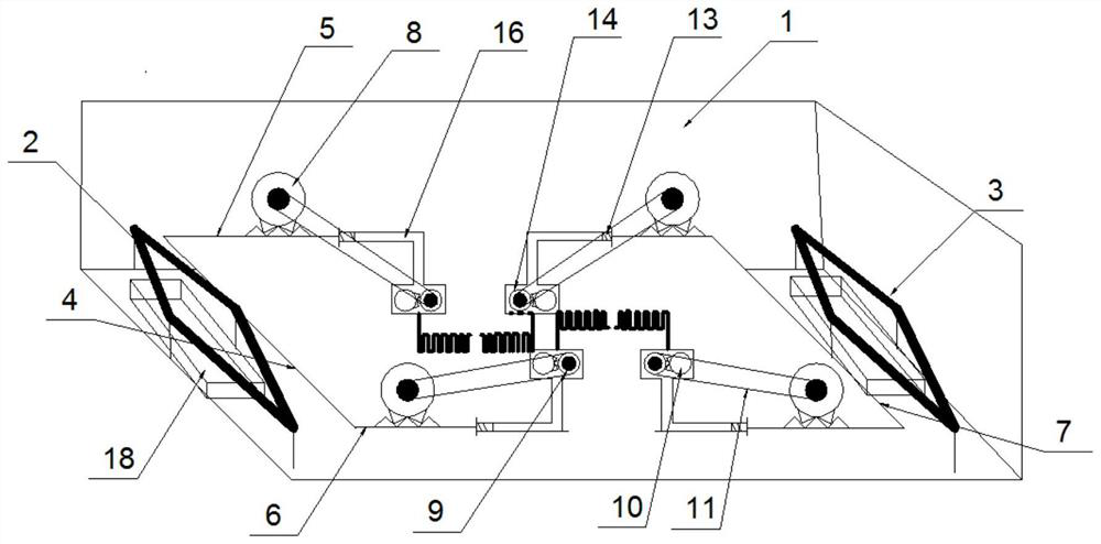
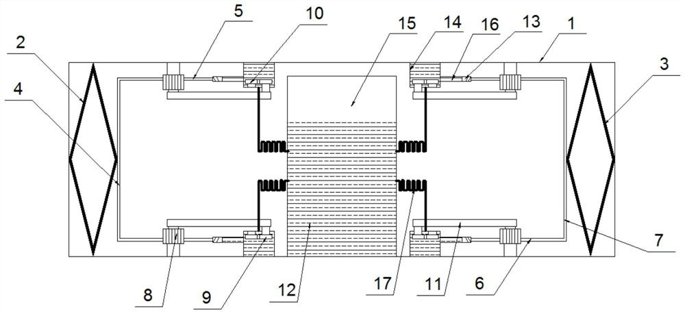
[0026] refer to figure 1 and figure 2 , a multi-directional vibration reduction and energy dissipation device, comprising a deformable housing 1, a vertically arranged left rhombus 2 hinged to the upper and lower side walls of the left end of the housing, and a horizontally pl...


PUM


Abstract

The device comprises a shell, a left rhombic piece hinged to the upper side wall and the lower side wall of the left end in the shell 1, and a U-shaped left push-pull rod hinged to the right end of the left rhombic piece, horizontally placed and provided with a rightward opening. The right rhombic piece is hinged to the upper side wall and the lower side wall of the right end in the shell, the right push-pull rod is hinged to the left end of the right rhombic piece, horizontally placed and provided with a leftward opening in a U shape, and the magneto-rheological energy dissipation assembly is arranged between the left push-pull rod and the right push-pull rod. Straight teeth are arranged on the side walls of the free ends of the upper arms and the lower arms of the left push-pull rod and the right push-pull rod, flywheels meshed with the straight teeth of the upper arms and the lower arms are arranged on the upper side wall and the lower side wall in the shell, and a first belt pulley is arranged on each flywheel shaft. The magneto-rheological energy dissipation assembly comprises four first liquid storage containers, a driving gear and a driven gear which are meshed are arranged in each first liquid storage container, a driving gear shaft extends out of the first liquid storage container to be connected with a second belt pulley, and belts are arranged on the first belt pulley and the second belt pulley. And each first liquid storage container is filled with magnetorheological fluid.

Description

technical field [0001] The invention relates to the field of vibration reduction and disaster reduction of engineering structures, in particular to a multi-directional vibration reduction and energy consumption device. Background technique [0002] With the acceleration of economic development and urbanization, engineering structures are developing towards higher heights, larger spans, and more complex structural forms. However, natural disasters such as earthquakes, strong winds, and tsunamis will cause large multi-directional vibrations of these structures, which seriously affect the safety and comfort requirements of the structures. Contents of the invention [0003] In order to solve the above problems, the present invention provides a multi-directional vibration reduction and energy consumption device. The multi-directional vibration reduction and energy consumption device can reduce the large multi-directional vibration of the engineering structure caused by natural ...

Claims


Application Information

Patent Timeline
IPC IPC(8): E04B1/98E04H9/02
Inventor 傅博徐浩然苏杭斌庄芷丹郭子菡秦颢毓
Owner CHANGAN UNIV
Learn More