Oily sludge treatment equipment

A sludge treatment and equipment technology, applied in sludge treatment, water/sludge/sewage treatment, sludge treatment through temperature control, etc., can solve the problems of wasting time incinerating energy, affecting incineration efficiency, and high energy consumption. Achieve the effects of saving production costs and labor productivity, protecting the ecological environment, and high resource recovery rates

Active Publication Date: 2021-09-07
CHONGQING WATER RESOURCES & ELECTRIC ENG COLLEGE
View PDF31 Cites 2 Cited by
  • Summary
  • Abstract
  • Description
  • Claims
  • Application Information

AI Technical Summary

Problems solved by technology

[0002] At present, large-scale oily sludge treatment equipment is mainly used for environmental protection treatment of oily sludge in large-scale sludge treatment plants. It has high cost, large floor space, and requires multiple operators to operate. Therefore, it is not suitable for small, fast Treatment of Oily Sludge
At the same time, in the prior art, there are also some metering rooms, oil transfer stations or well site maintenance teams that use small incinerators to incinerate a small amount of oily sludge, and after the incineration reaches the standard, subsequent disposal such as burial is carried out; however, this direct Incineration of oily sludge, firstly, the crude oil contained in the sludge is not recovered, resulting in energy waste; secondly, the water content of the wet sludge is relatively high, which affects the incineration efficiency, wastes time and incineration energy; thirdly, it is easy to generate Pollution gas, causing environmental pollution
Moreover, for the current mainstream oily sludge treatment equipment, the process of sludge compression and extrusion requires a high-power motor to drive the equipment to run, which consumes a lot of energy and has low efficiency, which greatly wastes production costs.

Method used


Image

  • Oily sludge treatment equipment
  • Oily sludge treatment equipment
  • Oily sludge treatment equipment

Examples


Embodiment Construction

[0025] The following will clearly and completely describe the technical solutions in the embodiments of the present invention with reference to the accompanying drawings in the embodiments of the present invention. Obviously, the described embodiments are only some, not all, embodiments of the present invention. Based on the embodiments of the present invention, all other embodiments obtained by persons of ordinary skill in the art without making creative efforts belong to the protection scope of the present invention.

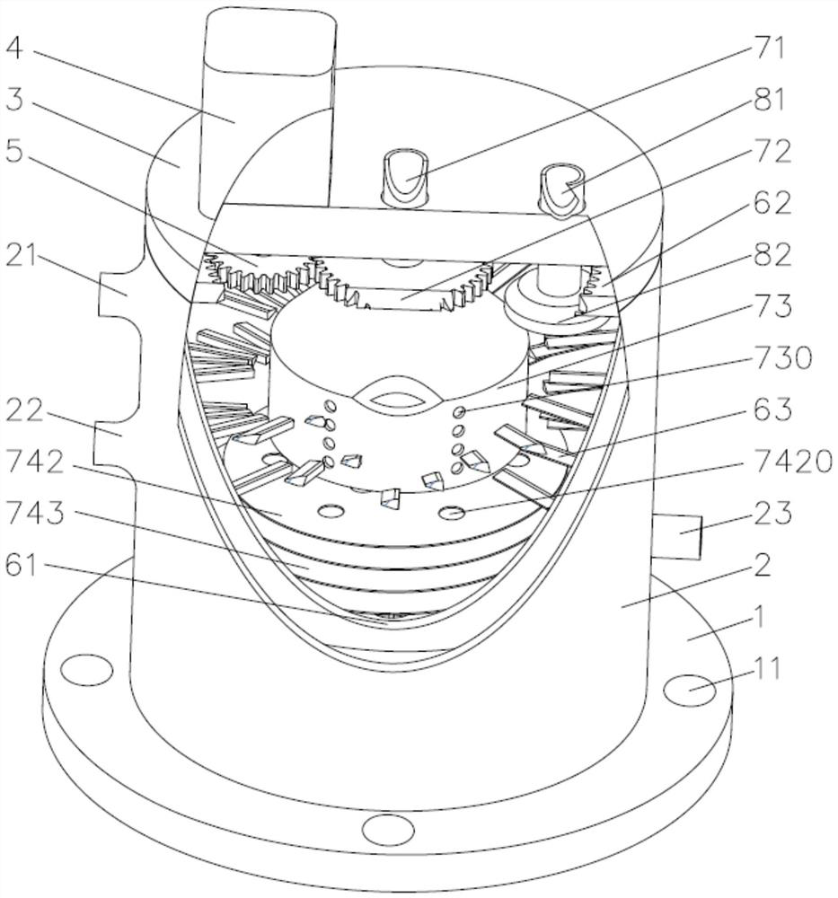
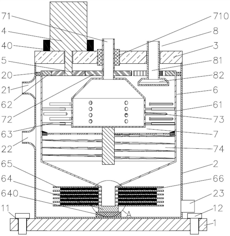
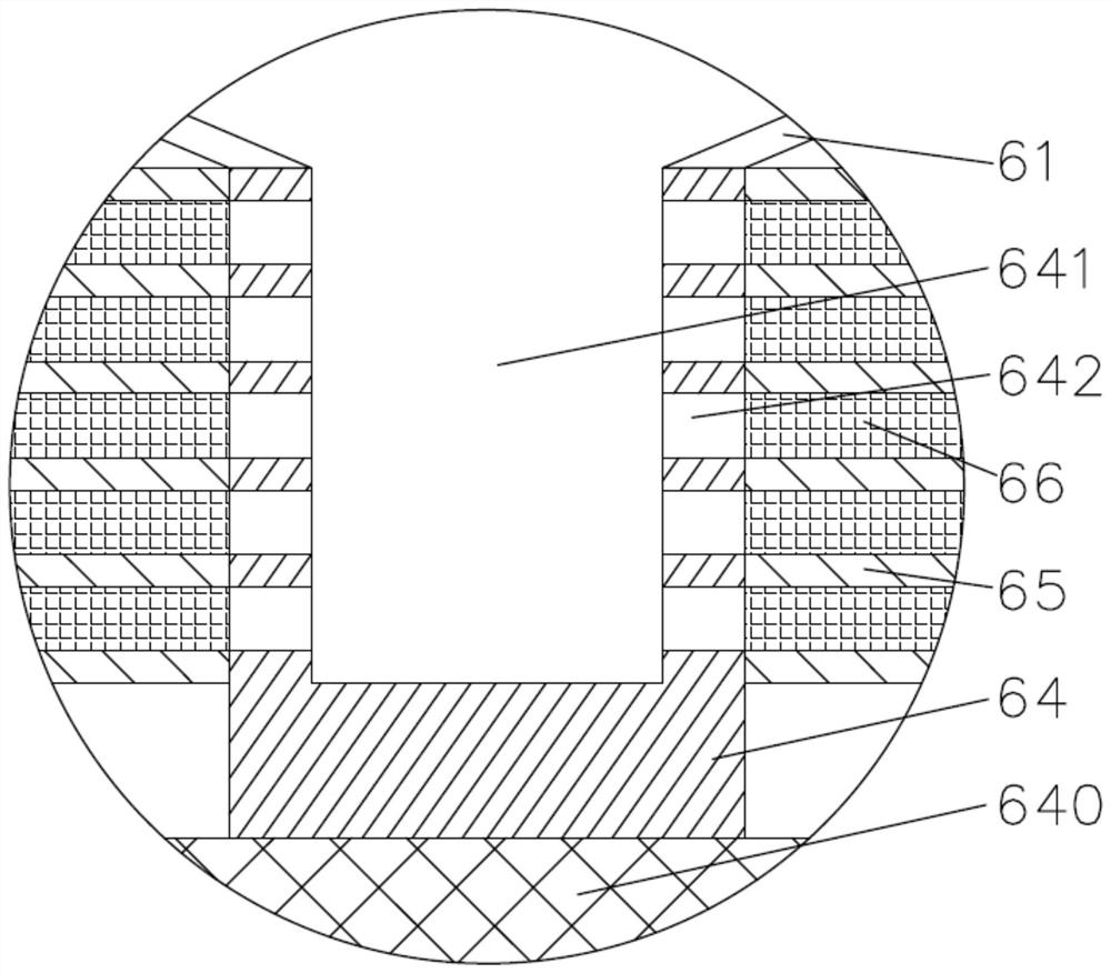
[0026] Such as Figure 1~5 As shown, an oily sludge treatment equipment is characterized in that it includes a base 1, an oil separation main body 2, an end cover 3, a drive motor 4, a drive gear 5, a separation part 6 and a dispersion part 7; the oil separation main body 2 is fixed Installed on the upper end surface of the base 1 and the top of the oil separation main body 2 is provided with an end cover 3, the driving motor 4 is fixedly installed on one side...


PUM


Abstract

The invention provides oily sludge treatment equipment. The oily sludge treatment equipment comprises a base (1), an oil stain separation main body (2), an end cover (3), a driving motor (4), a driving gear (5), a separation part (6) and a dispersion part (7), wherein the separation part (6) is arranged in the oil stain separation main body (2) and comprises a separation cavity (61), a gear ring (62), wedge-shaped teeth (63), a supporting separation shaft (64), a separation disc (65) and fins (66); the dispersing part (7) is arranged in the separating part (6) and comprises a feeding pipe (71), a driven gear (72), a dispersing cavity (73) and a spiral blade assembly (74), and the spiral blade assembly (74) comprises a connecting mandrel (741), a partition plate (742) and a spiral blade (743). The equipment is convenient to move, suitable for treating a small amount or a large amount of oily sludge, high in oily sludge treatment efficiency, low in energy consumption, free of environmental pollution in the treatment process and high in resource recovery rate.

Description

technical field [0001] The invention relates to the technical field of sludge treatment devices, in particular to oily sludge treatment equipment. Background technique [0002] At present, large-scale oily sludge treatment equipment is mainly used for environmental protection treatment of oily sludge in large-scale sludge treatment plants. It has high cost, large floor space, and requires multiple operators to operate. Therefore, it is not suitable for small, fast Treatment of oily sludge. At the same time, in the prior art, there are also some metering rooms, oil transfer stations or well site maintenance teams that use small incinerators to incinerate a small amount of oily sludge, and after the incineration reaches the standard, subsequent disposal such as burial is carried out; however, this direct Incineration of oily sludge, firstly, the crude oil contained in the sludge is not recovered, resulting in energy waste; secondly, the water content of the wet sludge is rela...

Claims


Application Information

Patent Timeline
Patent Type & Authority Applications(China)
IPC IPC(8): C02F11/00C02F11/127C02F11/18C02F101/30
CPCC02F11/00C02F11/127C02F11/18C02F2101/30
Inventor 汤超关娇娇
Owner CHONGQING WATER RESOURCES & ELECTRIC ENG COLLEGE
Why Eureka
Try Eureka