
Hydrogen impurity removal device based on hydrogen refueling station

A technology for hydrogen refueling station and gas supply device, which is applied in hydrogen separation, gas treatment, hydrogen separation by selective and reversible absorption, etc., can solve the problems of reducing battery life, poisoning of catalysts and membrane electrodes, irreversibility, etc.

Active Publication Date: 2021-09-07
深圳国氢新能源科技有限公司
View PDF8 Cites 0 Cited by
  • Summary
  • Abstract
  • Description
  • Claims
  • Application Information

AI Technical Summary

Problems solved by technology

[0002] The core components of the fuel cell have extremely high requirements on the impurity content in the hydrogen source. Impurity gases such as H2S, CO, CO2, and N2 in the hydrogen source will seriously affect the service performance and life of the fuel cell. For example, sulfur-containing impurities will make the fuel cell catalyst and membrane electrode Poisoning and irreversibility, greatly reducing the service life of the battery, is one of the problems that fuel cells are difficult to solve
[0003] At present, the hydrogen used in fuel cell hydrogen refueling stations is mainly industrial high-purity hydrogen transported by long-tube trailers. The impurity content in hydrogen remains constant after multiple process conversions, especially H2S has an impact on the use of fuel hydrogen, and further research is needed. Cleaning reduces the content of H2S and improves the purity of hydrogen, but the hydrogen purification of the hydrogen refueling station is not mature, and the maintenance cost is high

Method used


Image

  • Hydrogen impurity removal device based on hydrogen refueling station
  • Hydrogen impurity removal device based on hydrogen refueling station
  • Hydrogen impurity removal device based on hydrogen refueling station

Examples


Embodiment Construction

[0025] The present invention will be further described below in conjunction with the accompanying drawings and embodiments.

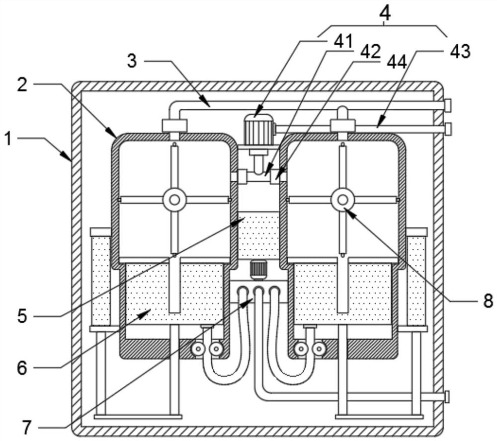
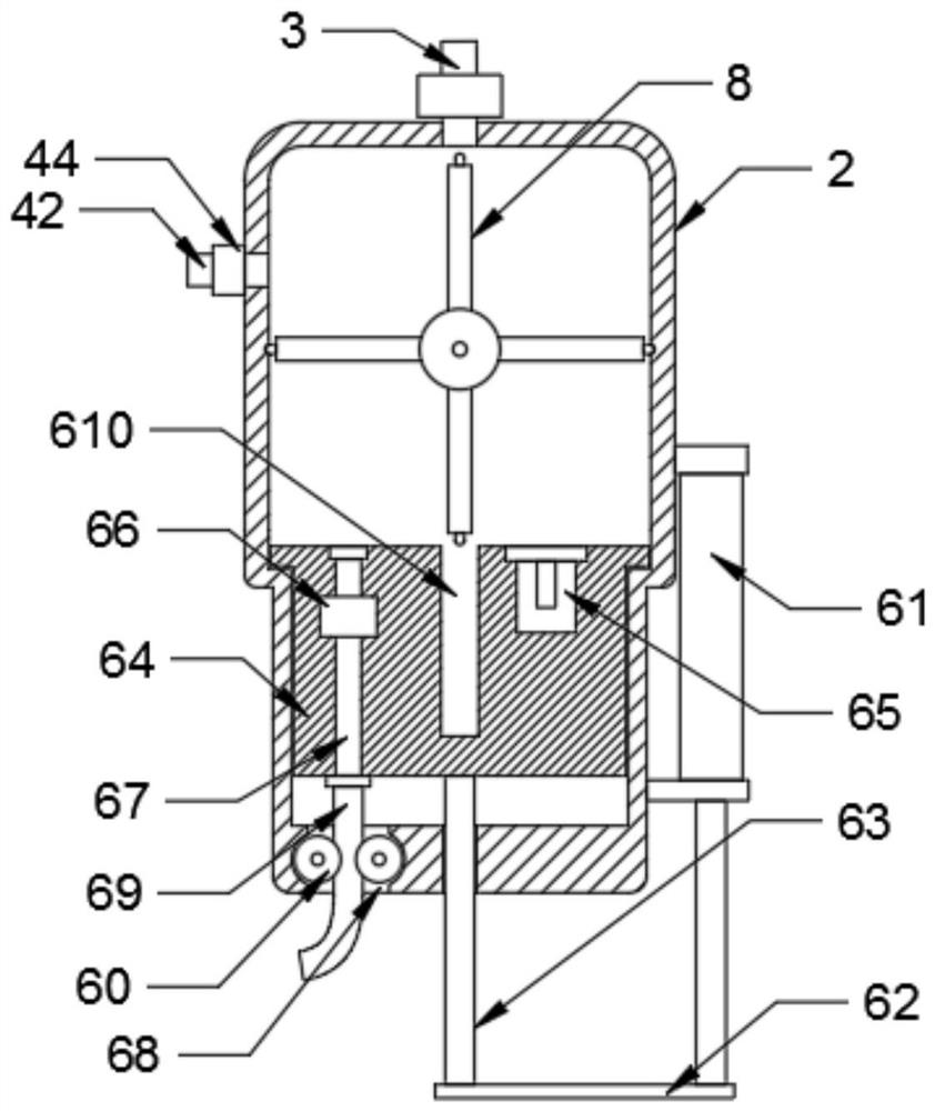
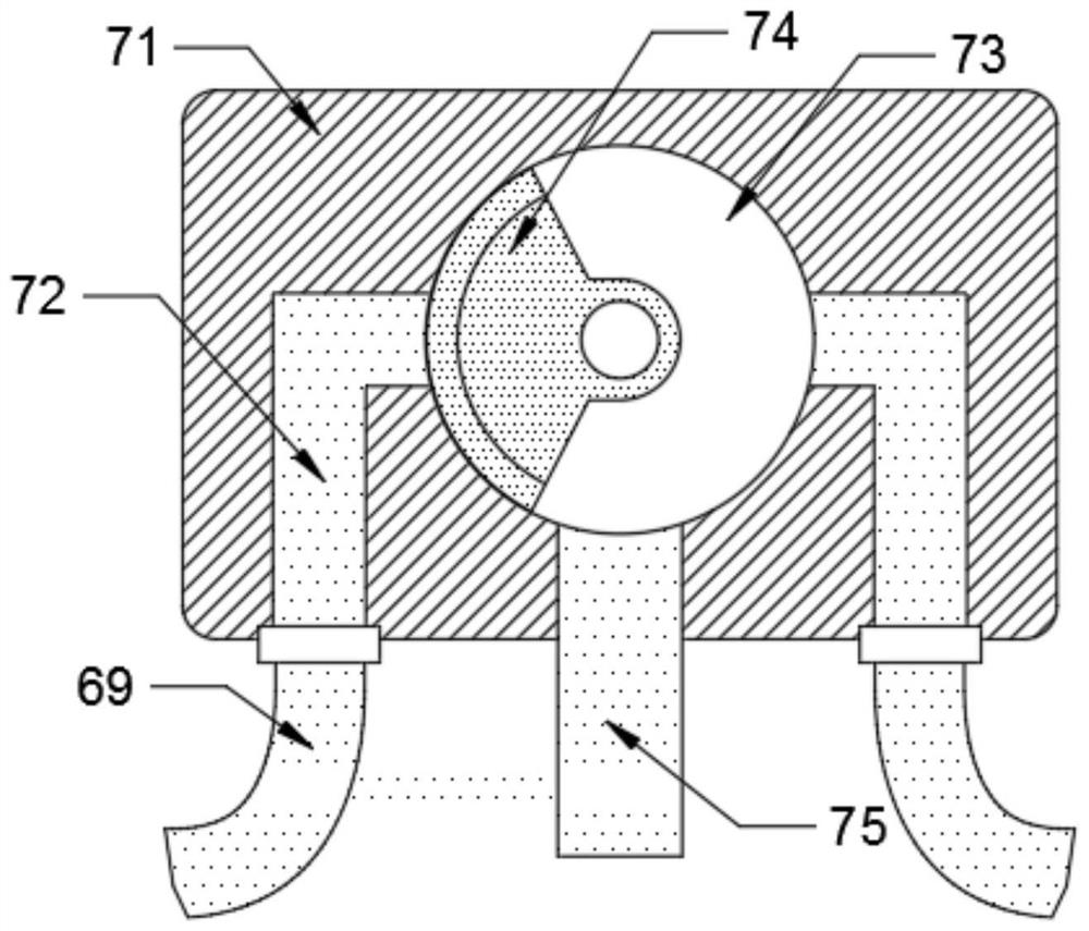
[0026] Please refer to figure 1 , figure 2 , image 3 , Figure 4 , Figure 5 and Figure 6 ,in, figure 1 A schematic diagram of the overall structure provided for the present invention; figure 2 Schematic diagram of the structure of the auxiliary row device provided by the present invention; image 3 One of the structural schematic diagrams of the gas supply device provided by the present invention; Figure 4 The second schematic diagram of the structure of the gas supply device provided by the present invention; Figure 5 One of the structural schematic diagrams of the purification device provided by the present invention; Figure 6 The second schematic diagram of the purification device structure provided by the present invention. Including: outer box 1, filter tank 2, exhaust pipe 3 and controller 5.

[0027] In the specific implementat...


PUM


Abstract

The invention provides a hydrogen impurity removal device based on a hydrogen refueling station. The hydrogen impurity removal device based on the hydrogen refueling station comprises an outer box, filtering tanks, an exhaust pipe and a controller, the filtering tanks are symmetrically fixed to the inner wall of the outer box, the tops of the filtering tanks are connected with the exhaust pipe, and the controller is installed between the filtering tanks. The device is characterized in that a purifying device is mounted at the top end in each filtering tank, a pressure regulating device is mounted at the upper part between the filtering tanks,an auxiliary discharging device is mounted at the bottom of each filtering tank, and an air supply device is mounted at the lower part between the filtering tanks. The two filtering tanks are matched with the gas supply device to alternately supply gas, it is guaranteed that the purification device in one filtering tank works, the purification device in the other filtering tank is repaired, uninterrupted purification processing of hydrogen is completed, high efficiency of work is guaranteed, and the equipment is simple in structure. And by arranging the two working parts, later-stage non-stop maintenance is facilitated, and the maintenance cost is reduced.

Description

technical field [0001] The invention relates to the field of hydrogen purification, in particular to a hydrogen impurity removal device based on a hydrogen refueling station. Background technique [0002] The core components of the fuel cell have extremely high requirements on the impurity content in the hydrogen source. Impurity gases such as H2S, CO, CO2, and N2 in the hydrogen source will seriously affect the service performance and life of the fuel cell. For example, sulfur-containing impurities will make the fuel cell catalyst and membrane electrode Poisoning and irreversibility, greatly reducing the service life of the battery, is one of the problems that fuel cells are difficult to solve. [0003] At present, the hydrogen used in fuel cell hydrogen refueling stations is mainly industrial high-purity hydrogen transported by long-tube trailers. The impurity content in hydrogen remains constant after multiple process conversions, especially H2S has an impact on the use o...

Claims


Application Information

Patent Timeline
IPC IPC(8): B01D53/02C01B3/50
CPCB01D53/02C01B3/508B01D2253/108B01D2256/16
Inventor 郭彭旭李刚曾广彬王成林郭玉平
Owner 深圳国氢新能源科技有限公司
Learn More