
Multi-cavity concrete column and construction method thereof

A concrete column and concrete technology, applied in the direction of columns, pier columns, pillars, etc., can solve the problems of accelerated corrosion of wall decoration materials, many construction procedures, and difficult construction, etc., to achieve easy construction and installation, good mechanical performance, and simple construction Effect

Pending Publication Date: 2021-09-03
HUAQIAO UNIVERSITY
View PDF0 Cites 0 Cited by
  • Summary
  • Abstract
  • Description
  • Claims
  • Application Information

AI Technical Summary

Problems solved by technology

In order to meet the mechanical performance of the traditional single steel pipe concrete column, the cross section of the steel pipe needs to be set very large or very thick, which leads to high cost, heavy weight and long construction period
[0003] At the same time, in order to enhance the bonding performance between the steel pipe and concrete or strengthen the connection between the internal section steel and the external steel pipe, the traditional steel pipe concrete column usually chooses to install stiffeners, inner partitions or studs inside the steel pipe, which is not easy to construct.
In addition, when the traditional CFST column is connected to the filled wall, steel bars are usually used to tie it, or to weld the slot connection at the joint position of the CFST column, which is troublesome in construction and requires many construction procedures; One side is located indoors, and one side is located outdoors. Due to the good thermal conductivity of steel, a cold and heat bridge effect may be formed at the connection position, which may easily cause the wall decoration materials to be damp and accelerate corrosion.

Method used


Image

  • Multi-cavity concrete column and construction method thereof
  • Multi-cavity concrete column and construction method thereof
  • Multi-cavity concrete column and construction method thereof

Examples


Embodiment 1

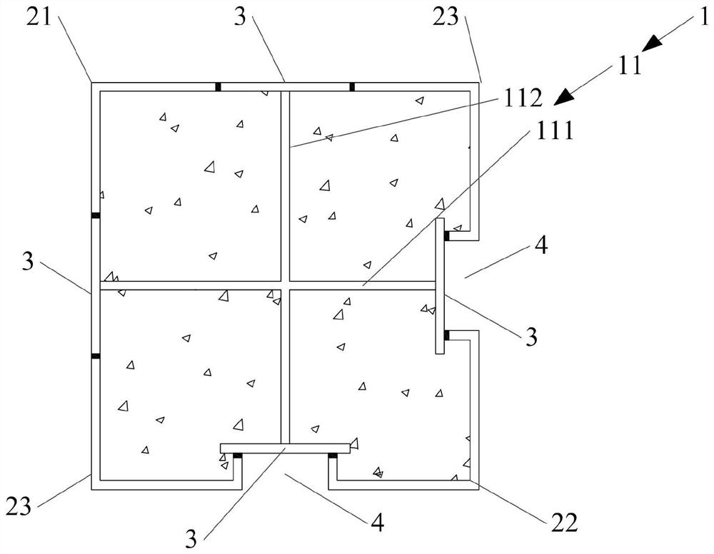
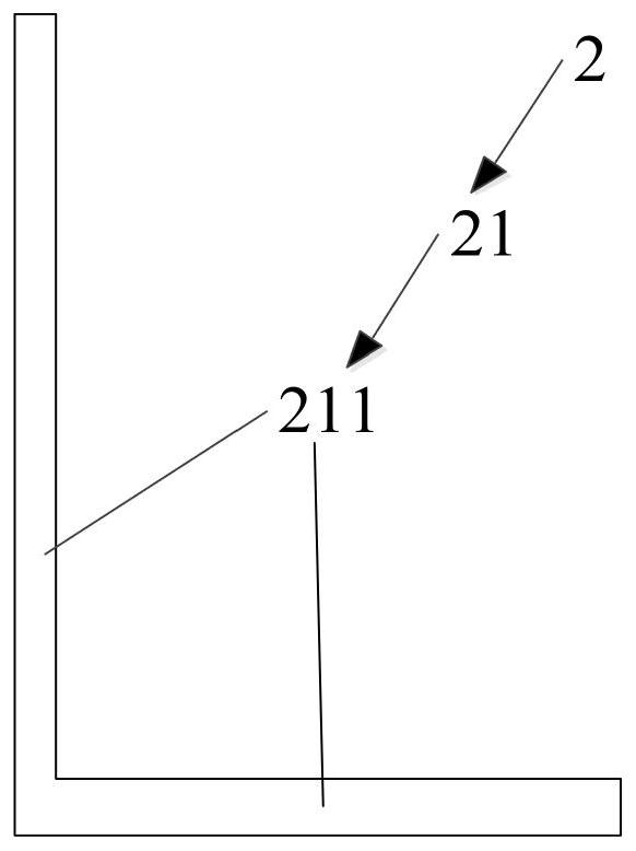
[0031] This embodiment provides a multi-cavity concrete column, please refer to figure 1 , including a support 1, at least one external plate 2 and at least one flange 3, the support 1 includes at least one plate, each side end of the plate is fixedly provided with a flange 3, two adjacent wings The flange plates 3 are fixedly connected by an external plate 2; the support member 1, the flange plate 3 and the external plate 2 form a cavity column with at least two cavities, and each cavity is used to be filled with concrete. And at least one outer cavity wall of the cavity column has a groove 4 for embedding with the filling wall.

[0032]The support member 1, the flange plate 3 and the outer plate 2 form a cavity column with at least two cavities, and then the cavity is filled with concrete to be cooled to form a concrete column. Setting multiple cavities can effectively restrain the core concrete shrinkage and joint cracking, and the plate body of support 1 can act as an inn...

Embodiment 2

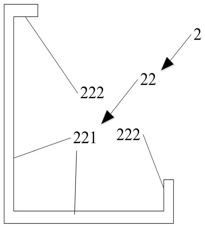
[0039] This embodiment provides another multi-cavity concrete column, see Figure 5 , the difference between this embodiment and Embodiment 1 is that: the four outer connecting plates 2 are all set as second outer connecting plates 22; a second outer connecting plate 22 is connected between adjacent flange plates 3, and each second The two second outer plates 222 of the outer connecting plate 22 are fixedly connected to the two adjacent flange plates 3 respectively, and the two second outer plates 222 close to each other between the adjacent second outer connecting plates 2 are connected to the same wing The edge plate 3 also forms a groove 4, that is, the number of grooves 4 is four in total, and the four grooves 4 are respectively located on the four outer side walls of the multi-cavity concrete column; so set, the multi-cavity concrete provided by this embodiment The column can be used as the column in the inner cavity, and the four outer walls of the multi-cavity concrete ...

Embodiment 3

[0041] This embodiment also provides a multi-cavity concrete column, see Figure 6 , the difference between this embodiment and Embodiment 1 is that: the four external plates 2 are all set as the third external plate 23; a third external plate 23 is connected between adjacent flange plates 3, and the first plate body 111 Or the flange plate 3 connected to both ends of the second plate body 112 is fixedly connected to the third outer plate 232 and forms two opposite grooves 4, and the two grooves 4 are located on the two opposite outer walls of the multi-cavity concrete column Above; set up in this way, the multi-cavity concrete column provided by this embodiment can be used as the middle column of the outer wall, and the opposite outer wall of the multi-cavity concrete column is embedded and connected with two filling walls through two grooves 4 .


PUM


Abstract

The invention relates to the technical field of building structures, in particular to a multi-cavity concrete column. The concrete column comprises a supporting piece, at least one external connecting plate and at least one flange plate, wherein, the supporting piece comprises at least one plate body, one flange plate is fixedly arranged at the side end of each plate body, and every two adjacent flange plates are fixedly connected through one external connecting plate; a cavity column with at least two cavities is defined by the supporting piece, the flange plates and the external connecting plates, each cavity is filled with concrete, and at least one outer cavity wall of the cavity column is provided with a groove used for being fixedly embedded into a filler wall. The multi-cavity concrete column is simple in structure, good in stress performance and convenient in installation and construction; and the effect of relieving the cold and hot bridge effect can be achieved after the grooves and the filler wall are embedded and fixed. The invention further provides a construction method of the multi-cavity concrete column.

Description

technical field [0001] The invention relates to the technical field of building structures, in particular to a multi-cavity concrete column and a construction method thereof. Background technique [0002] With the progress of society, the building structure develops towards the direction of towering and large span. In order to meet the mechanical performance of the traditional single-steel concrete column, the cross-section of the steel pipe needs to be set very large or very thick, which leads to high cost, heavy weight and long construction period. [0003] At the same time, in order to enhance the bonding performance between the steel pipe and concrete or strengthen the connection between the internal section steel and the external steel pipe, the traditional steel pipe concrete column usually chooses to install stiffeners, inner partitions or studs inside the steel pipe, which is not easy to construct. In addition, when the traditional CFST column is connected to the fi...

Claims


Application Information

Patent Timeline
Patent Type & Authority Applications(China)
IPC IPC(8): E04C3/36
CPCE04C3/36
Inventor 王卫华鲁亚彪祁神军左帅陈翔泰张智勇
Owner HUAQIAO UNIVERSITY
Learn More