Waste mineral oil purification device and purification method thereof
A waste mineral oil and purification device technology, applied in the field of comprehensive utilization of waste mineral oil resources, can solve the problems of low processing efficiency, slow temperature rise, and unstable process
- Summary
- Abstract
- Description
- Claims
- Application Information
AI Technical Summary
Problems solved by technology
Method used
Image
Examples
Embodiment 1
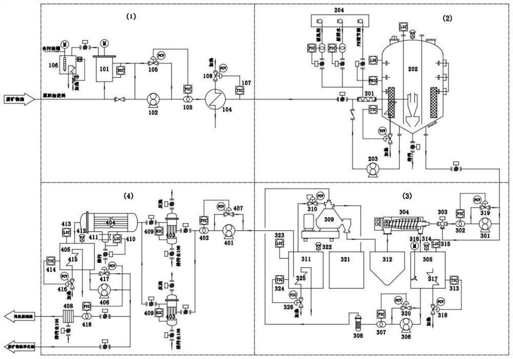
[0045] Embodiments of the present invention provide a waste mineral oil purification device and purification method thereof, such as Figure 1-Figure 6 As shown, it is characterized in that it includes four unit modules including instant heating unit 1, conditioning unit 2, separation unit 3 and security unit 4, and the instant heating unit 1, conditioning unit 2, separation unit 3 and security unit 4 are sequentially connected;
[0046] The instant heating unit 1 and the modulation unit 2 are arranged on the lower platform, the separation unit 3 and the security unit 4 are arranged on the upper platform, and the lower platform and the upper platform are combined to form a two-layer process frame platform;
[0047] The waste mineral oil purification device is automatically controlled by an intelligent control system composed of PLC or DCS, display control instruments, valves and process pipelines.
[0048] The beneficial effect of above-mentioned technical scheme is:
[004...
Embodiment 2
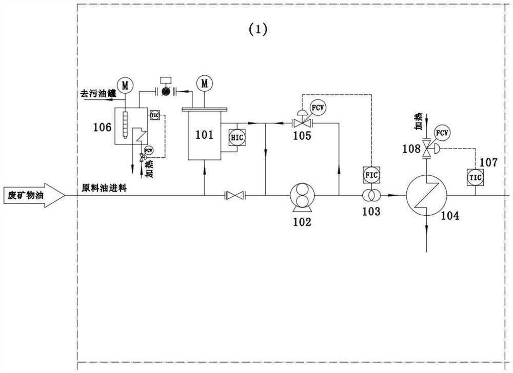
[0055] On the basis of Example 1, such as Figure 1-Figure 2 As shown, the instant heat unit 1 includes a self-cleaning filter 101, a raw material pump 102, a flow meter one 103 and a fast heat exchanger group 104 connected sequentially through process pipelines according to the flow direction of waste mineral oil, and the fast heat exchanger The group 104 is connected with the tempering unit 2, and the self-cleaning filter 101 is communicated with the self-temperature-controlled dirty oil recovery device 106 through the sewage discharge process pipeline; the raw material pump 102 and the flow meter 103 are respectively connected with the flow regulating valve-105, and A temperature display control instrument 107 is installed on the outlet pipeline of the rapid heat exchanger group 104, and the rapid heat exchanger group 104 is connected with the heat medium flow regulating valve 108 through the temperature display control instrument 107. Group 104 is one or more spiral plate ...
Embodiment 3
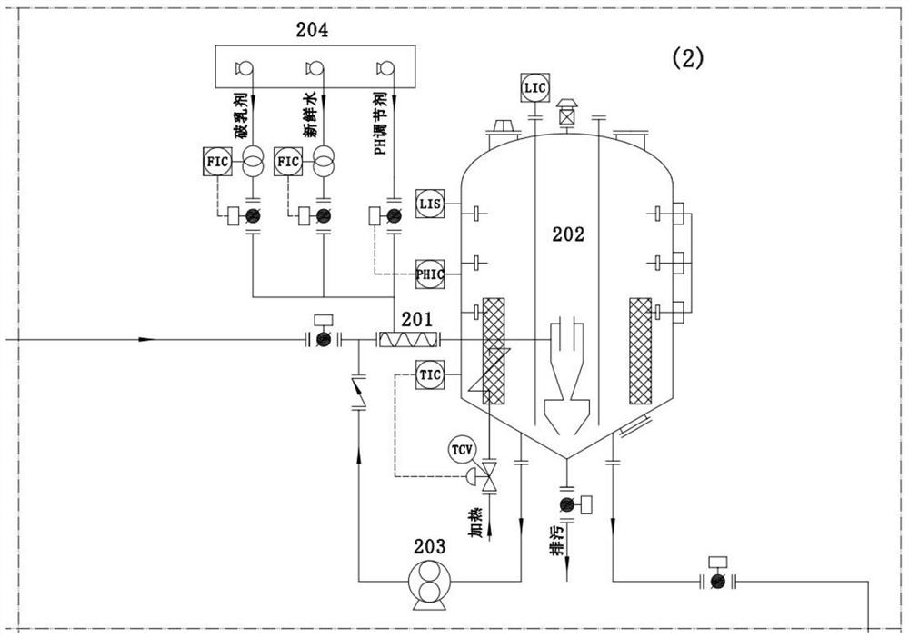
[0059] On the basis of Example 1, such as figure 1 , image 3 , Figure 6 As shown, the conditioning unit 2 can be connected in one or more parallel ways, and the conditioning unit 2 includes a static mixer 201, a conditioning tank 202 and a circulating Pump 203, the static mixer 201 is provided with a number of medicament inlets, the static mixer 201 is connected to the medicament automatic dosing device 204 through a number of medicament inlets, and the circulation pump 203 is connected to the static mixing device through a process pipeline. Device 201 is connected;
[0060] The tempering tank 202 includes an elliptical head 2001, a cylinder body 2002, a conical head 2003 and legs 2004 sequentially connected from top to bottom, and the lower end of the conical head 2003 is provided with a manhole 2019 and a sewage outlet 2020 And oil outlet 2021 and circulation port 2022, described circulation port 2022 is connected with described circulation pump 203 through process pipe...
PUM
 Abstract
Description
Claims
Application Information
 - Generate Ideas
- Intellectual Property
- Life Sciences
- Materials
- Tech Scout
- Unparalleled Data Quality
- Higher Quality Content
- 60% Fewer Hallucinations
Browse by: Latest US Patents, China's latest patents, Technical Efficacy Thesaurus, Application Domain, Technology Topic, Popular Technical Reports.
© 2025 PatSnap. All rights reserved.Legal|Privacy policy|Modern Slavery Act Transparency Statement|Sitemap|About US| Contact US: help@patsnap.com


