
CSP online die bonder

A die-bonding machine and die-bonding technology, used in electrical components, circuits, semiconductor devices, etc., can solve the problems of equipment jitter, poor stability, and large equipment size, and achieve the effects of reducing vibration, high stability, and reducing operation difficulty.

Pending Publication Date: 2021-08-31
SHENZHEN GRANDSEED TECH DEV
View PDF0 Cites 0 Cited by
  • Summary
  • Abstract
  • Description
  • Claims
  • Application Information

AI Technical Summary

Problems solved by technology

[0005] There are the following problems in the prior art: the equipment is large in size, poor in stability, and the vibration is serious when the equipment is running at high speed

Method used


Image

  • CSP online die bonder
  • CSP online die bonder
  • CSP online die bonder

Examples


Embodiment Construction

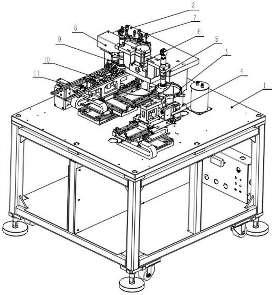
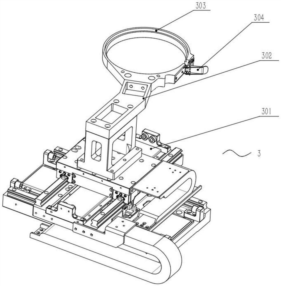
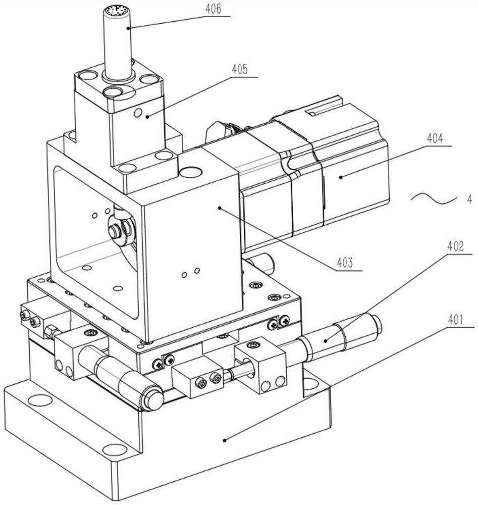
[0045] see Figure 1-11 , in the embodiment of the present invention, the CSP online crystal bonding machine includes a frame 1, a gantry frame 2, a wafer assembly 3, a thimble assembly 4, a feeding vision assembly 5, a swing arm assembly 6, a crystal bonding vision assembly 7, and a dispensing Component 8 , glue supply component 9 , die bonding component 10 and material supply positioning component 11 . The frame 1 plays a supporting role, the gantry 2 is fixed on one side of the top surface of the frame 1 , and the wafer assembly 3 is fixed on the top surface of the frame 1 and is located on one side of the gantry 2 . The thimble assembly 4 is fixed on one side of the wafer assembly 3 . The feeding visual assembly 5 is located above the wafer assembly 3 and is fixedly connected with the gantry 2 . The swing arm assembly 6 is located on one side of the loading vision assembly 5 and is fixedly connected with the gantry 2 . The crystal-bonding visual assembly 7 is located on...


PUM


Abstract

The invention discloses a CSP online die bonder, and belongs to the field of die bonders. The die bonder comprises a rack, a portal frame, a wafer disc assembly, an ejector pin assembly, a feeding visual assembly, a swing arm assembly, a die bonding visual assembly, a dispensing assembly, a glue supply assembly, a die bonding assembly and a supply positioning assembly. The rack plays a supporting role, the portal frame is fixed on one side of the top end face of the rack, and the crystal disc assembly is fixed on the top end face of the rack and located on one side of the portal frame. The ejector pin assembly is fixed on one side of the crystal disc assembly; the feeding visual assembly is located above the crystal disc assembly and fixedly connected with the portal frame. The swing arm assembly is located on one side of the feeding visual assembly and fixedly connected with the portal frame. The die bonding visual assembly is located on the side, away from the feeding visual assembly, of the swing arm assembly and fixedly connected with the portal frame. By arranging a series of structures, the equipment structure is simplified, the operation stability of the equipment is improved, the shaking of the equipment during high-speed operation can be reduced, and the die bonding accuracy is improved.

Description

technical field [0001] The invention relates to a crystal bonder, in particular to a CSP online crystal bonder. Background technique [0002] With the rapid development of the economy and the continuous progress of the society, energy conservation, emission reduction, efficiency increase and speed up have become an inevitable trend of global development, and the society has broad consensus on this. All kinds of electrical appliances are more and more developed in the direction of saving energy, being convenient to use, saving space, being safe and efficient, and having multiple functions in one machine. LEDs should be widely used in today's society, and there is great potential for energy saving. [0003] CSP packaging is the cutting-edge technology of existing LED production, which refers to a packaging technology in which the volume of the package itself does not exceed 20% of the size of the chip itself. In order to achieve this goal, LED manufacturers reduce unnecessar...

Claims


Application Information

Patent Timeline
Patent Type & Authority Applications(China)
IPC IPC(8): H01L33/48H01L33/62
CPCH01L33/48H01L33/62H01L2933/0033H01L2933/0066
Inventor 胡稳胡牛凡徐金宏杨帅黄锦钿
Owner SHENZHEN GRANDSEED TECH DEV
Learn More