
Logging image filling method and device, medium and electronic equipment

A logging image and mask image technology, applied in the field of image processing, can solve problems such as low efficiency, high cost, and poor filling quality

Active Publication Date: 2021-08-31
CHINA OILFIELD SERVICES
View PDF8 Cites 0 Cited by
  • Summary
  • Abstract
  • Description
  • Claims
  • Application Information

AI Technical Summary

Problems solved by technology

[0004] However, at present, the artificial method is mainly used to fill the digital image of acoustic-electric imaging logging, which is low in efficiency and high in cost. If the restoration personnel are inexperienced, it will also lead to poor filling quality

Method used


Image

  • Logging image filling method and device, medium and electronic equipment
  • Logging image filling method and device, medium and electronic equipment
  • Logging image filling method and device, medium and electronic equipment

Examples


Embodiment Construction

[0037] Reference will now be made in detail to the exemplary embodiments, examples of which are illustrated in the accompanying drawings. When the following description refers to the accompanying drawings, the same numerals in different drawings refer to the same or similar elements unless otherwise indicated. The implementations described in the following exemplary examples do not represent all implementations consistent with the present invention. Rather, they are merely examples of apparatuses and methods consistent with aspects of the invention as recited in the appended claims.

[0038] Furthermore, the drawings are merely schematic illustrations of the present disclosure and are not necessarily drawn to scale. The same reference numerals in the drawings denote the same or similar parts, and thus repeated descriptions thereof will be omitted. Some of the block diagrams shown in the drawings are functional entities and do not necessarily correspond to physically or logic...


PUM


Abstract

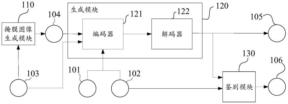
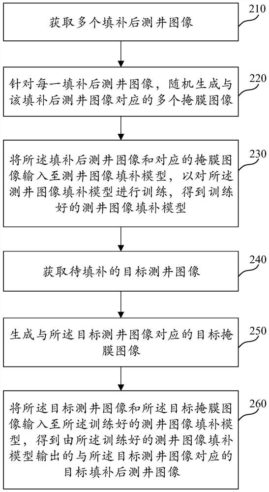
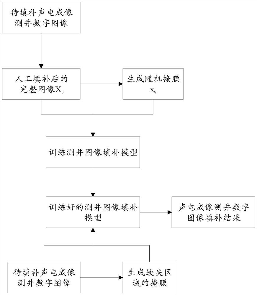
The invention relates to the field of image processing, and discloses a logging image filling method and device, a medium and electronic equipment. The method comprises the following steps: acquiring a plurality of filled logging images; randomly generating a mask image corresponding to the filled logging image; inputting the filled logging image and the mask image into a logging image filling model to train the logging image filling model to obtain a trained logging image filling model; obtaining a to-be-filled target logging image; generating a target mask image corresponding to the target logging image; and inputting the target logging image and the target mask image into the trained logging image filling model to obtain a target filled logging image which is output by the trained logging image filling model and corresponds to the target logging image. According to the method, automatic filling of the logging image can be realized, the filling quality is ensured, the efficiency of filling the logging image is improved, and the filling cost is reduced.

Description

technical field [0001] The present disclosure relates to the technical field of image processing, in particular to a logging image filling method, device, medium and electronic equipment. Background technique [0002] In well logging engineering, well logging images can more intuitively and clearly reflect the structure and characteristics of the wellbore. Geological problems that are difficult to solve with conventional logging can be dealt with more easily. However, due to the structure of the wellbore and the existing micro-resistivity imaging logging instrument, the instrument will be in an open state during the measurement, resulting in the inability to completely scan and collect the full image of the wellbore when scanning the acoustic-electric image of the borehole wall. It will lead to intermittent missing area blank bars on the image, resulting in partial information loss, which is not conducive to the later image processing and the identification of geological ph...

Claims


Application Information

Patent Timeline
IPC IPC(8): G06T5/00G06K9/62G06N3/04G06N3/08
CPCG06N3/08G06T2207/10004G06T2207/20081G06T2207/20084G06N3/045G06F18/214G06T5/80
Inventor 黄琳范川王显南侯振学陈鸣徐大年周全李炜王俊华张志强张传举张伟李恒王冬冬
Owner CHINA OILFIELD SERVICES
Learn More