
Waveform generator

A waveform generator and waveform technology, which is applied in the direction of instruments, pulse generation, radio wave measurement system, etc., can solve the problem of low occupancy efficiency of small memory areas

Pending Publication Date: 2021-08-31
STMICROELECTRONICS SRL
View PDF0 Cites 1 Cited by
  • Summary
  • Abstract
  • Description
  • Claims
  • Application Information

AI Technical Summary

Problems solved by technology

However, the area footprint of small blocks of memory is very inefficient because each block requires dedicated circuitry including row and column decoders, sense amplifiers, and reference generators

Method used


Image

  • Waveform generator
  • Waveform generator
  • Waveform generator

Examples


Embodiment Construction

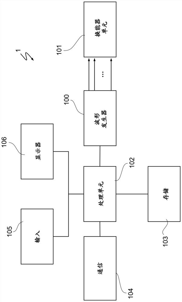
[0025] exist figure 1 An ultrasonic investigation apparatus according to an embodiment is illustrated in and designated by numeral 1 as a whole. The ultrasound investigation device 1 can be used, for example, in medical contrast-enhanced sonography or ultrasound examination of mechanical components. However, the invention is not limited to ultrasound applications and may be used to advantage in any situation involving waveform generators, in particular for driving multiple transducers with synchronized waveforms.

[0026] The ultrasonic investigation apparatus 1 includes a waveform generator 100 and a transducer unit 101 . The ultrasound investigation device 1 may further comprise a processing unit 102 , a storage unit 103 , a communication device 104 for remote communication (eg wired or wireless communication over a computer network), an input device 105 and a display 106 . In one embodiment, the waveform generator 100 and the transducer unit 101 may be integrated in the ...


PUM


Abstract

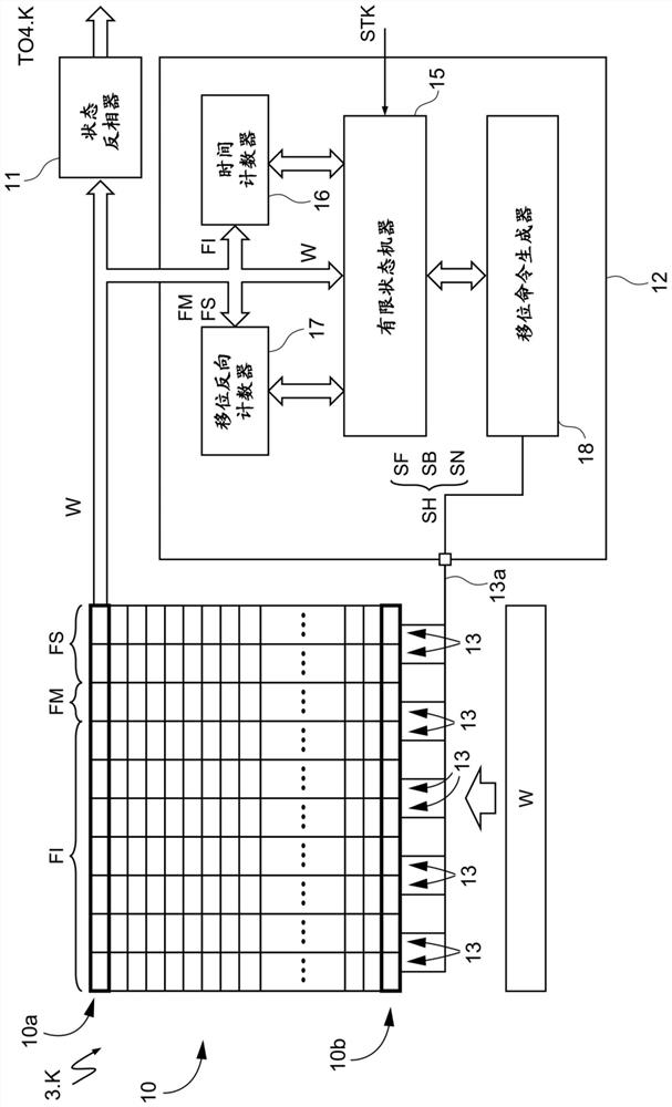
Embodiments of the disclosure relate to waveform generators. A waveform generator includes a system control unit and signal channels controlled by the system control unit and configured to supply driving signals for driving a respective transducer of an array of transducers. Each signal channel includes a sequential access memory having rows, wherein each row contains an instruction word configured to generate a respective step of a waveform to be generated. A memory output of the sequential access memory is defined by an output row at a fixed location. The waveform to be generated is defined by a block of instruction words. Each signal channel also includes an internal control unit that is configured to sequentially move the content of the sequential access memory, based on the instruction word currently at the memory output, so that sequences of instruction words are provided at the output row.

Description

[0001] priority claim [0002] This patent application claims the benefit of priority from Italian Patent Application No. 102020000004231 filed February 28, 2020, the contents of which are hereby incorporated by reference in their entirety to the fullest extent permitted by law. technical field [0003] The present invention relates to a waveform generator. Background technique [0004] Many applications are known to involve the use of waveform generators to drive transducer arrays. For example, in ultrasound imaging systems, linear or two-dimensional arrays of piezoelectric transducers are alternately used to generate an ultrasound beam and to receive the echoes produced by the beam's interaction with the object of interest. During the beamforming phase, the transducers are driven by a digital waveform generator and an analog pulse generator. A waveform is usually defined by a sequence of discrete values, such as two or more independent voltage values. For example, by u...

Claims


Application Information

Patent Timeline
Patent Type & Authority Applications(China)
IPC IPC(8): G01S7/52B06B1/02
CPCG01S7/5202B06B1/0215H03K4/026G01S7/524G06F9/3004G11C19/00G06F5/10G06F5/08G06F5/085
Inventor S·帕西R·G·巴尔代利A·莫罗尼
Owner STMICROELECTRONICS SRL
Learn More