
Multilayer dielectric structure for liver pathological section detection

A pathological slice, dielectric technology, applied in the optical field, can solve the problems of high cost, high false positive rate, long detection period, etc.

Pending Publication Date: 2021-08-31
HUBEI UNIV OF SCI & TECH
View PDF0 Cites 1 Cited by
  • Summary
  • Abstract
  • Description
  • Claims
  • Application Information

AI Technical Summary

Problems solved by technology

There are disadvantages such as long detection cycle, high false positive rate and high cost

Method used


Image

  • Multilayer dielectric structure for liver pathological section detection
  • Multilayer dielectric structure for liver pathological section detection
  • Multilayer dielectric structure for liver pathological section detection

Examples


Embodiment Construction

[0021] The following are specific embodiments of the present invention and in conjunction with the accompanying drawings, the technical solutions of the present invention are further described, but the present invention is not limited to these embodiments.

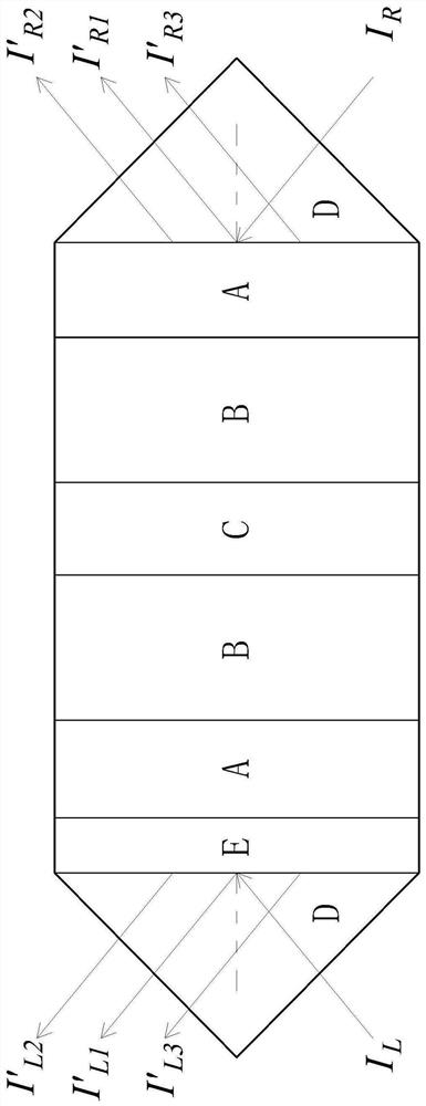
[0022] Arrange the two kinds of dielectrics, the first electrolyte layer A and the second electrolyte layer B, on both sides of the defect layer C to form an axisymmetric distribution about the dielectric C. Place the liver pathological slice E to be checked at the right end of this structure, such as figure 1 As shown, the symmetry of this structure is broken, but still retains some properties of photonic crystals, such as photonic band structure. This structure can also be recorded as EABCBA, where C is the defect layer of the photonic crystal. Two prismatic coupling waveguides D with an isosceles right triangle cross section are respectively placed at the left and right ends of the multilayer structure to improve the c...


PUM

PropertyMeasurementUnit
thicknessaaaaaaaaaa
thicknessaaaaaaaaaa
refractive indexaaaaaaaaaa

Abstract

The invention provides a multilayer dielectric structure for liver pathological section detection, and belongs to the technical field of optics. The multilayer dielectric structure includes a defect layer, two second dielectric layers located on the two sides of the defect layer respectively and two first dielectric layers located on the outer sides of the two second dielectric layers respectively; a prismatic coupling waveguide is arranged on the outer sides of the first dielectric layers, and the cross section of the prismatic coupling waveguide is in the shape of an isosceles right triangle; wherein a to-be-detected liver pathological section is inserted between one prismatic coupling waveguide and the first dielectric layer. According to the invention, the refractive index of the pathological section of the liver can be accurately measured through the spatial nonreciprocal Goos-Hansen displacement of the reflected light beam, so that quantitative analysis of the pathological section of the liver is realized.

Description

technical field [0001] The invention belongs to the field of optical technology, and relates to a multilayer dielectric structure used for detection of liver pathological slices. Background technique [0002] According to geometric optics, when light waves are at the interface of two different media, reflection and refraction phenomena will occur. Conversely, if the light beam is injected into the medium along the reflection or refraction optical path, at the interface, the original incident light path It is the path of reflected light or refracted light, which is the principle of reversible light path. That is, when a beam of light passes through an optical device, the beam of light forms a path for the light to travel. If the positions of the light source and the photodetector are exchanged, the light wave will return along the original path, which is the space reciprocity principle of the light wave. However, in a dielectric asymmetric structure with gain or loss, the r...

Claims


Application Information

Patent Timeline
Patent Type & Authority Applications(China)
IPC IPC(8): G01N21/41G01N21/01G02F1/00
CPCG01N21/01G01N21/41G01N2021/4173G02F1/0063
Inventor 李永逵
Owner HUBEI UNIV OF SCI & TECH
Learn More