
Hydraulic retarder with rotor with no-load loss reducing device

A hydraulic retarder and no-load loss technology, applied in the direction of liquid resistance brakes, fluid pressure actuators, brake types, etc., can solve the problems of reduced work efficiency, large proportion, increased power loss, etc., to achieve Reduced contact area, reduced idling loss, and obvious effect of loss reduction

Active Publication Date: 2021-08-31
JILIN UNIV
View PDF18 Cites 0 Cited by
  • Summary
  • Abstract
  • Description
  • Claims
  • Application Information

AI Technical Summary

Problems solved by technology

[0003] When the hydraulic retarder is not working, the idling loss accounts for a relatively large proportion compared with other mechanical losses, and the rotor of the hydraulic retarder is idling most of the time when the vehicle is running. If the problem of air loss is not solved, Vehicles equipped with retarders will reduce work efficiency due to increased power loss, so structural improvements to suppress air loss are necessary

Method used


Image

  • Hydraulic retarder with rotor with no-load loss reducing device
  • Hydraulic retarder with rotor with no-load loss reducing device
  • Hydraulic retarder with rotor with no-load loss reducing device

Examples


Embodiment Construction

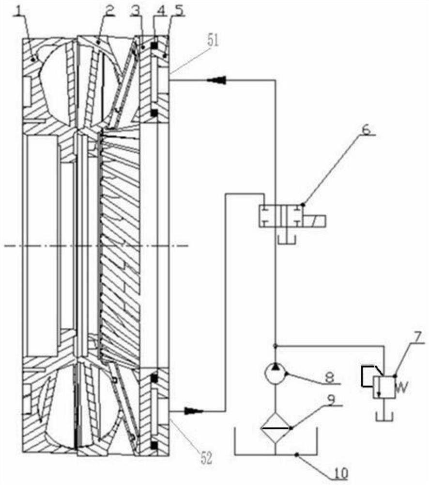
[0025] see Figure 1 to Figure 7 As shown, a hydraulic retarder with a rotor for reducing no-load loss includes a stator 1, a rotor 2, a first oil distribution mechanism 3, a sealing ring 4, a second oil distribution mechanism 5 and a hydraulic system, and the rotor 2 The first oil distributing mechanism 3 is fixedly arranged on the rotor 2, the second oil distributing mechanism 5 is rotatably arranged on the first oil distributing mechanism 3, the first oil distributing mechanism 3 and the second oil distributing mechanism 5 A sealing ring 4 is arranged between them, and the hydraulic system is connected with the second oil distribution mechanism 5;

[0026] Specifically, the first oil distribution mechanism 3 rotates synchronously with the rotor 2, and the second oil distribution mechanism 5 can rotate on the first oil distribution mechanism 3;

[0027] The rotor 2 is provided with an impeller, and several blade assemblies 16 are uniformly arranged on the impeller;

[0028...


PUM


Abstract

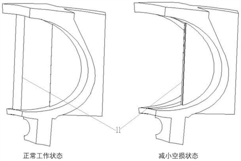
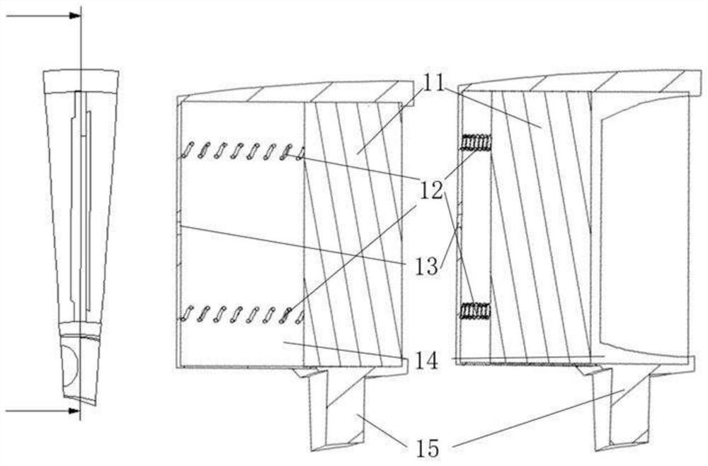
The invention discloses a hydraulic retarder with a rotor with a no-load loss reducing device. The hydraulic retarder comprises a stator, the rotor, a first oil distribution mechanism, a sealing ring, a second oil distribution mechanism and a hydraulic system, wherein the rotor is rotationally arranged on the stator; the first oil distribution mechanism is fixedly arranged on the rotor, and the second oil distribution mechanism is rotationally arranged on the first oil distribution mechanism; and the sealing ring is arranged between the first oil distribution mechanism and the second oil distribution mechanism, and the hydraulic system is connected with the second oil distribution mechanism. According to the hydraulic retarder with the rotor with the no-load loss reducing device, a rotor blade is designed to be of a telescopic structure, and when the hydraulic retarder idles, the rotor blade is adjusted to be in a retracted state, so that the contact area of air and the blade is reduced, and then idle loss is reduced; and according to CFD calculation, under the idle working condition that the rotating speed of the rotor is 1000 r / min, the braking torque can be reduced to 0.115 N.m from 5.127 N.m and the power can be reduced to 0.012 kW from 0.5368 kW by mounting the loss reducing device, and it can be seen that the loss reducing effect is obvious.

Description

technical field [0001] The invention belongs to the technical field of hydraulic transmission, in particular to a hydraulic retarder with a rotor for reducing no-load loss. Background technique [0002] The hydraulic retarder is an auxiliary braking system device for vehicles, which consists of two parts: a stator and a rotor. When the hydraulic retarder is in the braking state, the rotor rotates to drive the liquid to rotate and impact the stator, which converts the mechanical energy of the equipment into the heat energy of the liquid, and the stator generates a reaction force on the rotor through the liquid to generate braking torque. hinder the rotation of the rotor. When the vehicle is running normally, the hydraulic retarder is in the non-braking state, the retarder cavity is filled with air, and the rotor rotates to drive the air to impact the stator, which will produce a certain power loss. This power loss is idling power loss, referred to as idling power loss. loss...

Claims


Application Information

Patent Timeline
Patent Type & Authority Applications(China)
IPC IPC(8): F16D57/02F15B11/00F15B21/041
CPCF16D57/02F16D57/005F15B11/00F15B21/041F15B2211/205F15B2211/615
Inventor 马文星王佳欣刘春宝
Owner JILIN UNIV
Learn More