Turnover concrete silo structure steel bar accurate positioning device and method

A precise positioning and concrete technology, which is applied in building construction, on-site preparation of building components, formwork/formwork/working frame, etc., can solve problems such as fixed positioning of steel bars, hidden dangers of defects, and structural strength not up to standard. Achieve the effects of avoiding secondary rework, flexible and convenient disassembly, and high promotion and application value

Pending Publication Date: 2021-08-31
CHINA MCC5 GROUP CORP
View PDF0 Cites 0 Cited by
  • Summary
  • Abstract
  • Description
  • Claims
  • Application Information

AI Technical Summary

Problems solved by technology

[0002] In the field of construction, the slip-form construction process is a special construction process widely used in the construction of towering cast-in-place concrete structures; compared with conventional construction methods, this construction process has a high degree of mechanization, fast construction speed, and less site occupation. , strong structural integrity, good seismic performance, safe operation, remarkable comprehensive environmental and economic effects, can save the labor and materials required for setting up formwork and erecting scaffolding, can easily disassemble the formwork and assemble it flexibly, and can be reused, etc. ;Due to the high height of the steel bar in the current sliding form process, it is difficult to fix and position the steel bar. Therefore, the position of the steel bar will be deflected after pouring, resulting in the overall structural strength not reaching the standard, causing bad hidden dangers. Therefore, it is urgently needed A device and method for precise positioning of steel bars in a turnable concrete silo structure capable of guiding and positioning steel bars during the sliding form process

Method used


Image

  • Turnover concrete silo structure steel bar accurate positioning device and method
  • Turnover concrete silo structure steel bar accurate positioning device and method
  • Turnover concrete silo structure steel bar accurate positioning device and method

Examples


Embodiment 1

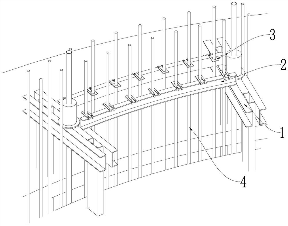
[0033] Example 1: See Figure 1 to Figure 4 , a precise positioning device for the steel bars of a turnable concrete silo structure in this embodiment, a fixed channel steel 2 is arranged across the sliding formwork operation platform 1, and a plurality of detachable guiding and positioning steel plates 3 are arranged on the fixed channel steel 2, and the guide The positioning steel plate 3 is provided with a fixing hole 31 for socketing the steel bar 4, and the perforation direction of the fixing hole 31 is parallel to the lifting direction of the sliding form operation platform 1; Compared with the previous construction method of positioning the horizontal and vertical steel bars 4 during the main construction of the building structure, during the construction process of the concrete silo structure silo wall sliding up, the construction method of precise positioning of the concrete silo structure steel bars 4 that can be reused is adopted, and the installation is convenient ...

Embodiment 2

[0034]Embodiment 2: The fixed channel steel 2 of this embodiment is an arc structure, and is attached to the inner arc surface of the silo. There are two fixed channel steels 2 in this embodiment, which are arranged in parallel on the sliding form operating platform 1 . The guiding and positioning steel plates 3 on the two fixing channel steels 2 of this embodiment are arranged oppositely, and the guiding and positioning steel plates 3 are all arranged between the two fixing channel steels 2 . The guiding and positioning steel plate 3 has a U-shaped structure, and is fixed on the fixed channel steel 2 by bolt clamping. It has high strength, good fixing effect, accurate position, and the positioning device can be turned over and reused. The guiding and positioning steel plate 3 of this embodiment includes a fixing frame 32 and first fixing parts 33 arranged at both ends of the fixing frame 32 , and the first fixing part 33 is connected to the fixing channel steel 2 by bolts. A...

Embodiment 3

[0035] Embodiment 3: The fixed channel steel 2 of this embodiment is provided with a second fixing part, and the first fixing part 33 includes an upper fixing plate 331, a connecting part 332 and a lower fixing plate 333, and the upper fixing plate 331 and the lower fixing plate 333 pass through The connecting portion 332 is fixed, and the upper fixing plate 331 is parallel to the lower fixing plate 333 , and the upper fixing plate 331 and the lower fixing plate 333 are used to sandwich the second fixing portion. In this embodiment, the upper fixing plate 331 is provided with bolt holes, through which the bolts pass through the bolt holes, and then abut and fix against the second fixing part. The fixed channel steel 2 in this embodiment is provided with a circumferential dimension scale for positioning and guiding the fixed steel plate. It is used to accurately locate the distance between the vertical and horizontal steel bars 4 during the sliding process, and at the same time...


PUM


Abstract

The invention discloses a turnover concrete silo structure steel bar accurate positioning device and method. Fixed channel steel is arranged on a slip form operation platform in a crossing mode, a plurality of detachable guide positioning steel plates are arranged on the fixed channel steel, fixing holes used for being connected with steel bars in a sleeved mode are formed in the guide positioning steel plates, and the perforating direction of the fixing holes is parallel to the lifting direction of the slip form operating platform; and a plurality of guide positioning steel plates are uniformly arranged on the fixed channel steel at intervals. Compared with a conventional construction method for positioning horizontal and vertical reinforcing steel bars during construction of a building structure main body, the construction method for accurately positioning the concrete silo structure reinforcing steel bars in a turnover manner is adopted in the sliding and lifting construction process of the silo wall of the concrete silo structure, installation is convenient, dismounting and changing are flexible, positioning is accurate, displacement is not prone to occurring, modular construction is achieved, labor is reduced, the construction cost is reduced, the engineering construction quality is improved, rework losses are reduced, and the management cost is reduced.

Description

technical field [0001] The invention relates to the field of silo pouring, in particular to a device and method for precise positioning of steel bars in a turnable concrete silo structure. Background technique [0002] In the field of construction, the slip-form construction process is a special construction process widely used in the construction of towering cast-in-place concrete structures; compared with conventional construction methods, this construction process has a high degree of mechanization, fast construction speed, and less site occupation. , strong structural integrity, good seismic performance, safe operation, remarkable comprehensive environmental and economic effects, can save the labor and materials required for setting up formwork and erecting scaffolding, can easily disassemble the formwork and assemble it flexibly, and can be reused, etc. ;Due to the high height of the steel bar in the current sliding form process, it is difficult to fix and position the ...

Claims


Application Information

Patent Timeline
Patent Type & Authority Applications(China)
IPC IPC(8): E04G21/12E04G21/18E04G11/22
CPCE04G11/22E04G21/12E04G21/1841
Inventor 李均谢长平刘宇陈昌俊陈磊
Owner CHINA MCC5 GROUP CORP
Why Eureka
Try Eureka