
Steel structure roof structure

A technology of roof structure and steel structure, applied in the direction of roof, roof drainage, roof, etc., can solve the problems of poor lighting performance, inconvenient cleaning, etc., and achieve the effect of ensuring light transmission, avoiding water seepage, and ensuring stability

Inactive Publication Date: 2021-08-31
李如
View PDF0 Cites 0 Cited by
  • Summary
  • Abstract
  • Description
  • Claims
  • Application Information

AI Technical Summary

Problems solved by technology

[0004] The steel structure roof in the prior art is mainly spliced ​​by steel plates. However, after the splicing is completed, its lighting performance is very poor. The traditional solution is to open lighting windows. However, the height of the factory building is usually above 6 meters. After the daylight window is covered with dust, it is very inconvenient to clean

Method used


Image

  • Steel structure roof structure
  • Steel structure roof structure
  • Steel structure roof structure

Examples


Embodiment 1

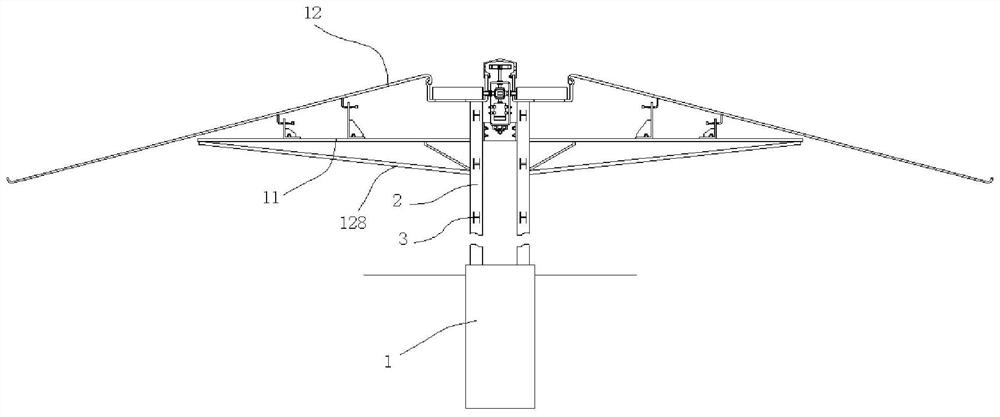
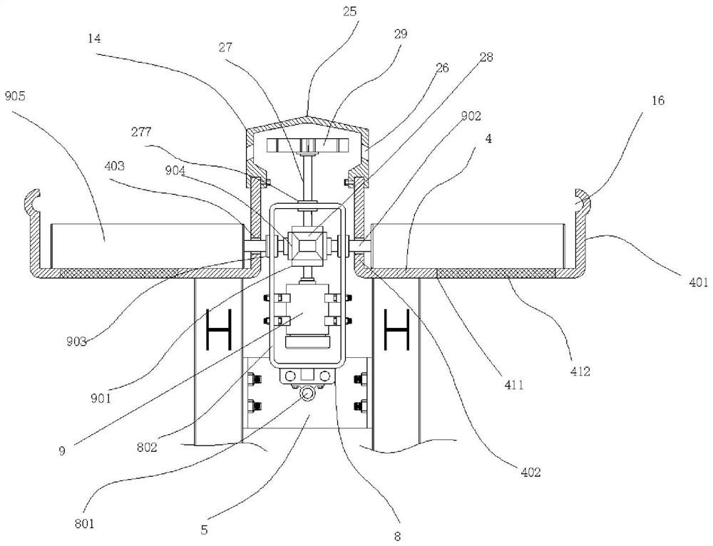
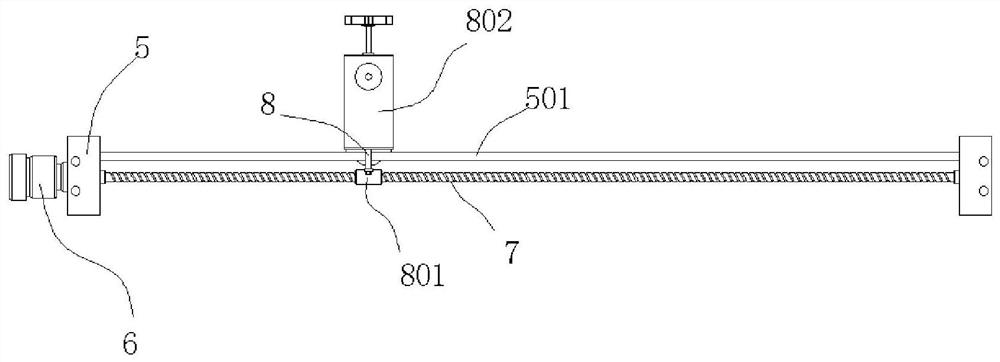
[0036]A steel structure roof structure, comprising concrete pouring and forming podiums 1, two left and right vertical bars 2 are poured in each of the podiums 1, and multiple podiums 1 are arranged at equal distances front and back; A connecting steel 3 is welded between the vertical bars 2, and a top plate 4 is welded between the tops of the front and rear adjacent vertical bars 2, and the outer side of the top plate 4 is bent upward to form an outer side plate 401, and the top plate The inner side of 4 is bent upwards to form an inner side plate 402, and a bar-shaped groove 403 is longitudinally arranged on the surface of the inner side plate 402; a bracket plate 5 is detachably assembled between the left and right adjacent vertical bars 2, A guide rail 501 is assembled between the front and rear two support plates 5; a servo motor 6 is installed at the end face of the support plate 5 on one side, and a lead screw 7 is connected to the output end of the servo motor 6, and th...

Embodiment 2

[0038] The cover plate 12 is arranged obliquely, and the inner side of the inner gusset 13 is provided with an arc-shaped convex strip 15; the side of the outer plate 401 is provided with an arc-shaped embedding groove 16, and the convex strip 15 is embedded in the In the embedding groove 16, at this time, the protruding strip 15 and the embedding groove 16 are installed in alignment to form a fit seal; an L-shaped adjustment plate 17 is welded on the bottom of the cover plate 12, and the adjustment The end of the plate 17 away from the cover plate 12 is provided with a tongue 18; a bolt 19 is welded on the top of the horizontal bar 11; an L-shaped movable plate 20 is assembled by the bolt 19, and the movable plate 20 has Cooperate with the U-shaped groove 21 of the bolt 19, the bolt 19 is fitted with a nut 22 after passing through the U-shaped groove 21, and the U-shaped groove 21 is arranged laterally; The socket 23 used for the tongue 18 is drilled with a threaded hole 232 ...

Embodiment 3

[0040] A rubber outer skin 151 is glued and fixed on the outside of the raised strip 15; the arrangement of the outer skin can further increase the sealing performance between the raised strip 15 and the embedded groove, increase the fit tightness, and reduce the water seepage rate at the same time.


PUM


Abstract

The invention discloses a steel structure roof structure. The steel structure roof structure comprises a plurality of pier bases formed through concrete pouring; a left vertical rod and a right vertical rod are poured in each pier base; the plurality of pier bases are arranged front and back at equal intervals; connecting steel is welded between front-back adjacent vertical rods; top plates are welded between the tops of the front-back adjacent vertical rods; the outer side of each top plate is bent upwards to form an outer side plate; the inner side of each top plate is bent upwards to form an inner side plate; strip-shaped grooves are longitudinally formed in the plate faces of the inner side plates; support plates are detachably assembled between left-right adjacent vertical rods; and guide rails are assembled between front and rear support plates. The structure can realize indoor lighting and is convenient to clean.

Description

technical field [0001] The invention relates to a steel structure roof structure. Background technique [0002] The roof refers to the roof of the house or structure, including the roof and all necessary materials and structures used to support the roof on the wall or other supports, which are used to resist natural rain, snow, wind, frost, solar radiation, temperature Changes and other unfavorable factors ensure a good environment for use inside the building. [0003] Steel structure roof is the most common roof structure in steel structure buildings, especially in steel structure factory buildings. At the beginning of design, steel structure roof can greatly reduce the layout cost, and it can be dismantled and recycled later. [0004] The steel structure roof in the prior art is mainly spliced ​​by steel plates. However, after the splicing is completed, its lighting performance is very poor. The traditional solution is to open lighting windows. However, the height of the ...

Claims


Application Information

Patent Timeline
Patent Type & Authority Applications(China)
IPC IPC(8): E04B7/00E04B7/02E04D13/03E04D13/04B08B1/04
CPCE04B7/00E04B7/02E04D13/03E04D13/04E04D2013/034B08B1/32
Inventor 李如
Owner 李如
Learn More