Temporary floating bridge capable of reducing water flow impact

A water impact and temporary technology, applied in the direction of pontoon bridges, bridges, bridge forms, etc., can solve the problems of pontoon shaking, poor stability, and greater influence of pontoon bridges, and achieve the effects of ensuring safety in use, improving stability, and preventing tipping

Inactive Publication Date: 2021-08-31
李子子
View PDF0 Cites 0 Cited by
  • Summary
  • Abstract
  • Description
  • Claims
  • Application Information

AI Technical Summary

Problems solved by technology

Temporary pontoon bridges are often used to pass through rivers temporarily. Temporary pontoon bridges are usually composed of splicing. The individual units are usually independent floating blocks, or floating blocks are combined with bridge decks, and the floating blocks and bridge decks are rigidly connected. As a result, the stability of this temporary bridge is poor, and the impact of the water flow has a greater impact on the pontoon bridge, causing the pontoon to shake violently, which in turn leads to poor use of the temporary pontoon bridge, difficulty in moving on the pontoon bridge, and the danger of falling into the water is extremely prone to occur. A temporary pontoon bridge composed of blocks, and the bridge deck often splashes a lot of water, which causes great difficulties for the bridge deck to move

Method used


Image

  • Temporary floating bridge capable of reducing water flow impact
  • Temporary floating bridge capable of reducing water flow impact
  • Temporary floating bridge capable of reducing water flow impact

Examples


Embodiment 1

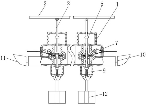
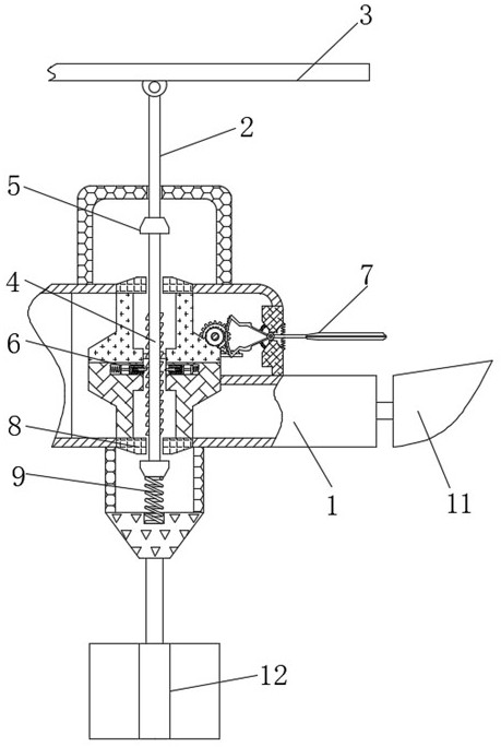
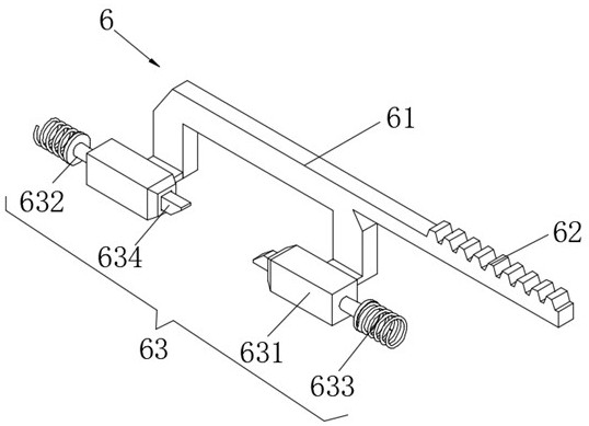
[0036] refer to Figure 2-4 , a temporary pontoon that can reduce the impact of water flow, including a floating block 1, the interior of the floating block 1 is movably connected with a limit rod 4, the outside of the limit rod 4 is provided with a force unloading mechanism 6, and the outside of the force unloading mechanism 6 is provided with an induction The mechanism 7 and the unloading mechanism 6 include a connecting rod 61 , the outside of the connecting rod 61 is fixedly connected with a toothed rod 62 , and the outside of the connecting rod 61 is fixedly connected with a limit mechanism 63 .

[0037] Wherein, the limit mechanism 63 includes a limit slider 631, the outside of the limit slider 631 is fixedly connected with a backing plate 632, and a return spring 633 is arranged between the back plate 632 and the floating block 1, and the limit slider 631 is slidably connected to Inside of float 1.

[0038] Wherein, the limit slider 631 slides inside the limit ratchet ...

Embodiment 2

[0043] refer to Figure 5 , a temporary pontoon that can reduce the impact of water flow, including a floating block 1, the interior of the floating block 1 is movably connected with a limit rod 4, the outside of the limit rod 4 is provided with a force unloading mechanism 6, and the outside of the force unloading mechanism 6 is provided with an induction The mechanism 7 and the unloading mechanism 6 include a connecting rod 61 , the outside of the connecting rod 61 is fixedly connected with a toothed rod 62 , and the outside of the connecting rod 61 is fixedly connected with a limit mechanism 63 .

[0044] Wherein, the induction mechanism 7 includes a sailboard 71, and the exterior of the sailboard 71 is fixedly connected with a fork shaft 72, the fork shaft 72 is hinged inside the floating block 1, and a seal is arranged between the fork shaft 72 and the outside of the floating block 1. Sleeve 73, swing spring 74 is arranged between fork shaft rod 72 and the inner side of floa...

Embodiment 3

[0050] refer to Figure 1-6 , a temporary pontoon that can reduce the impact of water flow, including a floating block 1, the interior of the floating block 1 is movably connected with a limit rod 4, the outside of the limit rod 4 is provided with a force unloading mechanism 6, and the outside of the force unloading mechanism 6 is provided with an induction The mechanism 7 and the unloading mechanism 6 include a connecting rod 61 , the outside of the connecting rod 61 is fixedly connected with a toothed rod 62 , and the outside of the connecting rod 61 is fixedly connected with a limit mechanism 63 .

[0051] Wherein, the limit mechanism 63 includes a limit slider 631, the outside of the limit slider 631 is fixedly connected with a backing plate 632, and a return spring 633 is arranged between the back plate 632 and the floating block 1, and the limit slider 631 is slidably connected to Inside of float 1.

[0052] Wherein, the limit slider 631 slides inside the limit ratchet ...


PUM


Abstract

The invention relates to the technical field of temporary floating bridges, and discloses a temporary floating bridge capable of reducing water flow impact, which comprises a floating block. A limiting rod is movably connected in the floating block, a force unloading mechanism is arranged outside the limiting rod, an induction mechanism is arranged outside the force unloading mechanism, and the force unloading mechanism comprises a connecting rod. The outer portion of the connecting rod is fixedly connected with a toothed bar, and the outer portion of the connecting rod is fixedly connected with a limiting mechanism. According to the temporary floating bridge capable of reducing the water flow impact, the right side is a wave peak, the left side is a wave valley, at the moment, a left side limiting mechanism of a limiting rod is separated from the limiting rod, a right side limiting mechanism makes contact with the limiting rod, a floating block can move upwards relative to the limiting rod, and when waves are in the reverse direction, the floating block can move downwards in the same way; therefore, the stability of the floating bridge can be guaranteed in the up-and-down fluctuating process of waves, and the use safety of the device is guaranteed.

Description

technical field [0001] The invention relates to the technical field of temporary floating bridges, in particular to a temporary floating bridge capable of reducing the impact of water flow. Background technique [0002] Floating bridges are bridges that use ships or pontoons instead of piers to float on the water surface. Floating bridges can be divided into temporary pontoon bridges and permanent pontoon bridges. Permanent pontoon bridges often have complex structures, and the stability of pontoon bridges is also guaranteed to a certain extent. Temporary pontoon bridges are often used to pass through rivers temporarily. Temporary pontoon bridges are usually composed of splicing. The individual units are usually independent floating blocks, or floating blocks are combined with bridge decks, and the floating blocks and bridge decks are rigidly connected. As a result, the stability of this temporary bridge is poor, and the impact of the water flow has a greater impact on the p...

Claims


Application Information

Patent Timeline
IPC IPC(8): E01D15/14E01D19/00E01D19/12F16F15/067
CPCE01D15/14E01D19/00E01D19/125F16F15/067
Inventor 李子子
Owner 李子子
Why Eureka
Try Eureka