Spinning bobbin wiring device
A wiring device, spool technology, used in transportation and packaging, transportation of filamentous materials, thin material handling, etc.
- Summary
- Abstract
- Description
- Claims
- Application Information
AI Technical Summary
Problems solved by technology
Method used
Image


Examples
specific Embodiment approach 1
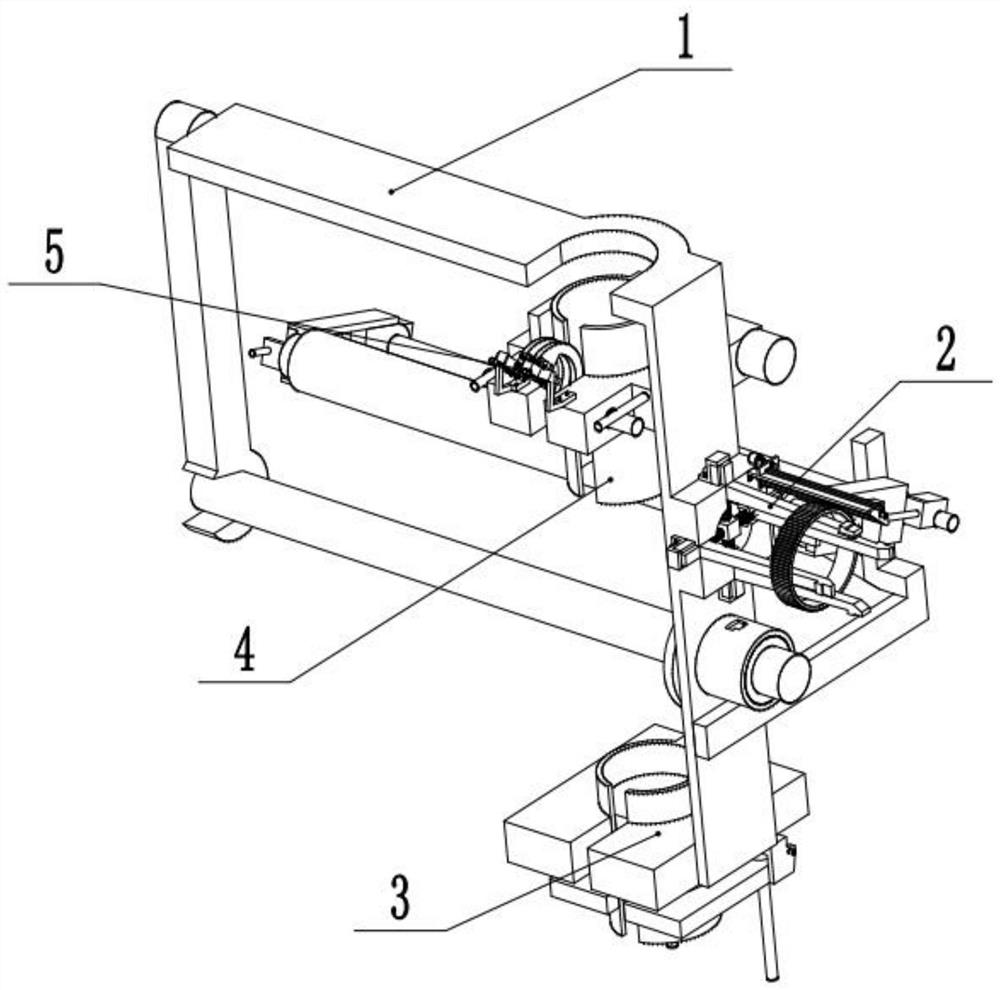
[0033] Combine below figure 1 , figure 2 , image 3 , Figure 4 , Figure 5 , Figure 6 , Figure 7 , Figure 8 , Figure 9 , Figure 10 , Figure 11 , Figure 12 , Figure 13 , Figure 14 To illustrate this embodiment, the present invention relates to a textile device, more specifically a textile spool wiring device, including a frame mechanism 1, a clamping mechanism 2, a lower thread mechanism 3, an upper thread mechanism 4, and a knotting mechanism 5 , the device can prevent the bobbin, the device can fix both ends of the thread, and the device can realize automatic knotting during the bobbin replacement process.
[0034] The clamping mechanism 2 is slidingly matched with the frame mechanism 1, the lower thread end mechanism 3 is fixed on the bottom of the frame mechanism 1, the upper thread end mechanism 4 is fixed on the top of the frame mechanism 1, and the knotting mechanism 5 is connected with the frame mechanism 1.
specific Embodiment approach 2
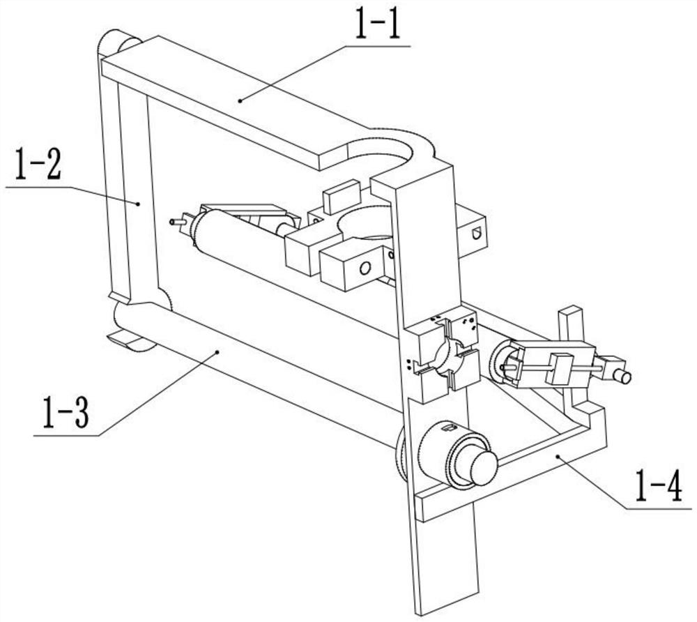
[0036] Combine below figure 1 , figure 2 , image 3 , Figure 4 , Figure 5 , Figure 6 , Figure 7 , Figure 8 , Figure 9 , Figure 10 , Figure 11 , Figure 12 , Figure 13 , Figure 14 Describe this embodiment, this embodiment will further explain the first embodiment, the frame mechanism 1 includes a main frame 1-1, a side frame 1-2, a roller 1-3, a rear frame 1-4, and a shaft 1-5 , sliding block 1-6, chute 1-7, pressing roller 1-8, spring straight rod 1-9, spring 1-10, telescopic motor 1-11, telescopic connecting rod 1-12, telescopic screw rod 1-13 , base 1-14, upper bracket 1-15, winding block 1-16, the main frame 1-1 is L-shaped, the top of the main frame 1-1 is provided with an arc, the side bracket 1-2 and the main frame 1-1 Rotation fit, roller 1-3 rotates with main frame 1-1, rear support 1-4 is fixed on the main frame 1-1, shaft 1-5 rotates with rear support 1-4, slide block 1-6 is set There are four, two sliding blocks 1-6 are fixed on the two ends...
specific Embodiment approach 3
[0038] Combine below figure 1 , figure 2 , image 3 , Figure 4 , Figure 5 , Figure 6 , Figure 7 , Figure 8 , Figure 9 , Figure 10 , Figure 11 , Figure 12 , Figure 13 , Figure 14 Describe this embodiment, this embodiment will further explain the first embodiment, the clamping mechanism 2 includes a clamping frame 2-1, a screw ring 2-2, a limit frame 2-3, a push-out spring 2-4, a screw Ring motor 2-5, screw column 2-6, screw belt 2-7, middle block 2-8, clamping frame 2-1 is provided with four, one end of clamping frame 2-1 is slidably matched with base 1-14, The outside of the clamping frame 2-1 is processed with teeth, the outside of the screw ring 2-2 is inclined, and the limit frame 2-3 is provided with four, the limit frame 2-3 is fixed on the base 1-14, and the spring 2 is pushed out. -4 is equipped with four, one end of the push-out spring 2-4 is connected with the clamping frame 2-1, one end of the push-out spring 2-4 is connected with the middle ...
PUM
 Abstract
Description
Claims
Application Information
 - R&D
- Intellectual Property
- Life Sciences
- Materials
- Tech Scout
- Unparalleled Data Quality
- Higher Quality Content
- 60% Fewer Hallucinations
Browse by: Latest US Patents, China's latest patents, Technical Efficacy Thesaurus, Application Domain, Technology Topic, Popular Technical Reports.
© 2025 PatSnap. All rights reserved.Legal|Privacy policy|Modern Slavery Act Transparency Statement|Sitemap|About US| Contact US: help@patsnap.com