Knotting Mechanism and Method for Knotting Rope for Carrying Paper Bag

A technology for stringing and paper bags, which is applied in the field of rope-threading knotting mechanism and stringing knotting for paper bags, can solve the problems of easy damage to the bag body, poor knot consistency, and inconvenient operation, and achieves a good degree of automation, Good consistency and improved convenience

Active Publication Date: 2016-12-21
杭州汇八科技有限公司
View PDF6 Cites 0 Cited by
  • Summary
  • Abstract
  • Description
  • Claims
  • Application Information

AI Technical Summary

Problems solved by technology

[0006] The invention provides a hand rope threading knotting mechanism and a handle rope threading knotting method for a portable paper bag that can thread the end of the handle rope into the bag body and knot the end of the handle rope. Solve the problems of easy damage to the bag body, inconvenient operation, and poor consistency of knots that exist in the manual rope-threading and knotting operations in the production process of portable paper bags

Method used


Image

  • Knotting Mechanism and Method for Knotting Rope for Carrying Paper Bag
  • Knotting Mechanism and Method for Knotting Rope for Carrying Paper Bag
  • Knotting Mechanism and Method for Knotting Rope for Carrying Paper Bag

Examples


Embodiment 1

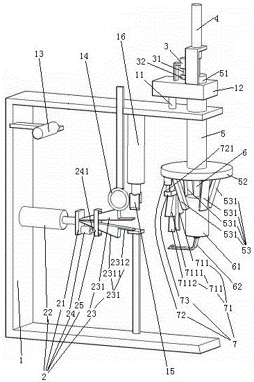
[0032] Example 1, see figure 1 , A hand-carrying rope threading and knotting mechanism for paper bags, comprising a frame 1. The frame 1 is provided with a rope threading manipulator 2, a first actuator 11, a rope coil mounting frame 13, a guide ring 14, a cutter 15 and a lifting seat 12 driven by the first actuator 11. The cutter 15 is connected to the frame 1 through a cutter driving cylinder 16.

[0033] The rope threading manipulator 2 includes a clip mounting seat 21 and a clip translation cylinder 22 connecting the clip mounting seat 21 to the frame 1. A rope threading clamp 23 and a rope threading clamp closing cylinder 24 are fixedly connected to the clamp mounting seat 21. The stringing clip 23 includes a pair of stringing clip pieces 231. The stringing clip 231 is an elastic steel sheet. The stringing clip 231 is connected together in a "eight" shape and is in a horizontal state. The stringing clip 231 is provided with a stringing clip closing control section 2311 a...

Embodiment 2

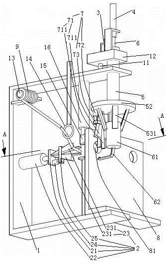
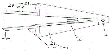
[0049] The second embodiment, the difference from the first embodiment is: see image 3 , The stringing clip 231 is hinged together by a hinge shaft 232. The outer surface of the stringing clip closing control section 2311 is a tapered surface. An expansion spring 233 is arranged between the pair of stringing clips 231. The free end surface 23121 of the chuck is a spherical surface. The pair of stringing clips 231 are kept in a separated state by opening the spring 233. The structural form of the rope-winding clamp constituting the rope-winding manipulator is the same as that of the rope-threading clamp.

[0050] See Figure 4 The rope withdrawal structure 53 includes a rope withdrawal ring 532 sleeved on the rope winding section 61 and a connecting rod 533 that suspends the rope withdrawal ring 532 on the turntable 52. The lifting rod 6 is provided with a suction channel 63 extending in the up and down direction. The inlet 631 of the suction channel is arranged on the side o...


PUM


Abstract

The present invention relates to a device and a method for connecting a handle cord to a bag body. A rope-threading knotting mechanism for a portable paper bag handle, comprising a frame, the frame is provided with a rope-threading manipulator, a first actuator, and an elevating seat driven by the first actuator, and the elevating seat is provided with a third actuator, a second The actuator, the vertical rotating shaft driven by the third actuator and the lifting rod driven by the second actuator, the lower end of the rotating shaft is connected to the turntable, the turntable is provided with a rope winding manipulator under it, and the lifting rod passes through. Rotating shaft, the lower end of handle bar stretches out rotating disk. The invention provides a portable paper bag handle rope threading knotting mechanism and a handle rope installation method that can pass the end of the handle rope into the bag body and knot the end of the handle rope, so as to solve the problem of In the production process, there are problems such as easy damage to the bag body, inconvenient operation, and poor consistency of knots in the manual rope-threading and knotting operations.

Description

Technical field [0001] The invention relates to a device and method for connecting a hand strap to a bag body, in particular to a threading and knotting mechanism for a hand-carrying paper bag and a threading and knotting method, belonging to the field of processing of hand-carrying paper bags. Background technique [0002] The existing portable paper bags have two structures for users to carry, one is a hand hole directly opened on the bag body, and the other is a hand connected to the bag body. [0003] In the Chinese patent number 2004200254298, the authorized announcement date is March 2, 2005, and the patent document named "carry paper bag", a paper bag consisting of a bag string (handle) and a bag body is disclosed. The connection between the bag body and the hand strap in the patent document is as follows: a rope hole is provided on the bag body, the two ends of the hand rope pass through the rope hole from the outside to the inside, and the end of the hand rope is provided ...

Claims


Application Information

Patent Timeline
Patent Type & Authority Patents(China)
IPC IPC(8): B31B1/86B31B50/86
Inventor 李璟
Owner 杭州汇八科技有限公司
Why Eureka
Try Eureka