Flash and image recorder with the flash

A technology of flashlight device and light source, which is applied in the direction of cameras, optics, optical components, etc., and can solve the problems of limited diffusion control state, difficult and difficult light irradiation angles, etc.

Inactive Publication Date: 2003-12-31
WEST ELECTRIC CO LTD
View PDF0 Cites 3 Cited by
  • Summary
  • Abstract
  • Description
  • Claims
  • Application Information

AI Technical Summary

Problems solved by technology

[0022] However, if the diffusion state of the outgoing light emitted from the rod-shaped light source is studied in detail, then the above-mentioned irradiation angle variable strobe device is also the same as the aforementioned existing device, in the horizontal direction as the wide-angle side, that is, in the longitudinal direction of the rod-shaped light source. There are still restrictions on the diffusion control state of the light emitted by the light source
As a result, there is a disadvantage that, for a photographic lens having a focal length shorter than a certain focal length, it becomes extremely difficult to set a light distribution characteristic having a light emission angle that can adequately cope with its photographic field of view, especially in wide-angle side photography , it is difficult to expand the light irradiation angle of the light distribution characteristic in the direction coincident with the above-mentioned longitudinal direction

Method used


Image

  • Flash and image recorder with the flash
  • Flash and image recorder with the flash
  • Flash and image recorder with the flash

Examples


Embodiment 1

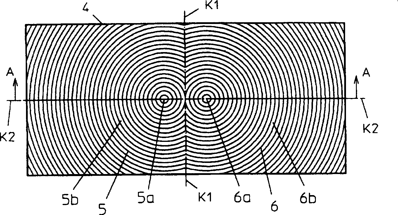
[0044] figure 1 , figure 2 It is a diagram schematically showing a specific example of the optical components of the key part of Embodiment 1 of the strobe device according to the present invention, respectively showing figure 1 Is a front view, figure 2 for figure 1 An enlarged cross-sectional view of the central part of the A-A section in the front view shown.

[0045] According to Embodiment 1 of the strobe device of the present invention, the figure 1 , figure 2 The optical member 4 shown is configured to include a changeable, for example, the front Picture 12 , Figure 13 The front of the well-known light-emitting unit such as the light-emitting irradiation angle variable means of the light-emitting irradiation angle mentioned above. That is, it is constructed by mounting the optical member 4 in front of the light-emitting unit, for example, by mounting it on an external casing not shown in the figure that can perform a variable operation of the light-emitting irradi...

Embodiment 2

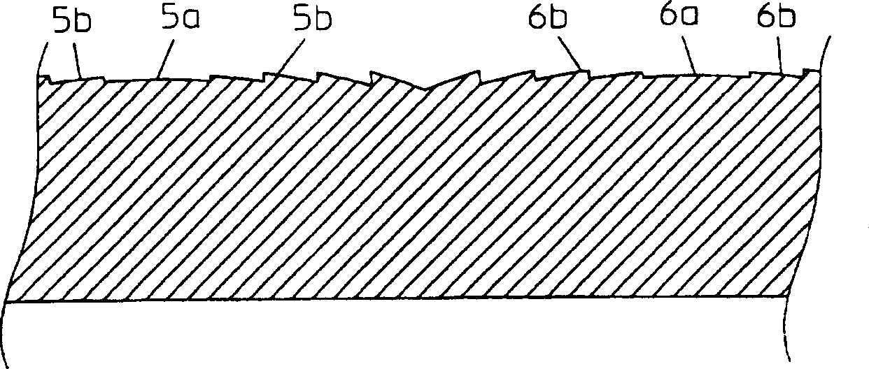
[0091] The optical member 4 of this embodiment is different from the optical member 4 used in the previous embodiment 1, and the first condensing lens unit 5 and the second condensing lens unit 6 have different configurations.

[0092] Such as Figure 4 As shown, the first condenser lens unit 5 and the second condenser lens unit 6 include first optical units 5A, 6A and second optical units 5B, 6B, each of the first optical units 5A, 6A has at least a vertex 5a, 6a, at the same time there is the first light-gathering characteristic. In the figure, the dashed diagonal line to the upper right is applied to show. The second optical units 5B and 6B are connected to the first optical units 5A and 6A and have the first light-gathering characteristic. The different second condensing characteristics are shown in the figure with a dashed oblique line toward the lower right.

[0093] Therefore, it is needless to say that the same function as the optical member 4 of the foregoing embodiment 1...

Embodiment 2

[0139] For Example 2, the vertices 12a, 13a of the optical member 11 are not necessarily set on the second reference line K2, and the vertices 12a, 13a can be moved to the second reference line K2 according to the desired light distribution characteristics. Below or above. Furthermore, when it is extremely difficult to configure the optical member 11 as a Fresnel lens, the optical member 11 may be configured to have a lens curved surface in which the first condenser lens unit 12 and the second condenser lens unit 13 are continuous.


PUM

PropertyMeasurementUnit
Outer diameteraaaaaaaaaa
Thicknessaaaaaaaaaa
Full lengthaaaaaaaaaa

Abstract

By more widely diffusing light from a rod light source, particularly in the direction of the length of the rod light source than conventional strobe lights and image recorders, a strobe light of the present invention and an image recorder containing the strobe light provide luminous intensity distribution characteristics including a light emitting angle large enough to cover, for example, landscape images and the angle of coverage of imaging lenses with a short focal length. This allows the light emitting angle in the direction of the length of the rod light source to increase during wide-angle imaging, with little variation in the luminous intensity distribution characteristics in the direction at right angles to the direction of the length of the rod light source, as compared with known-arrangement strobe lights.

Description

Technical field [0001] The present invention relates to a flash lamp whose illumination angle from a light source to an illuminated object can be changed and an image recording device incorporating the flash lamp. Background technique [0002] In the past, when photographing a subject as a photographic subject, an image recording device such as a photographic camera using a silver salt film used as a photosensitizer or a so-called electronic camera used as an electrical component of the photosensitizer was widely used, and such image recording was used. When the device photographs a subject, a flash device is useful as an artificial light source for illuminating such a subject. [0003] This strobe device is composed of a light-emitting unit and an optical component. The light-emitting unit is composed of a reflector formed by connecting an approximately parabolic reflective surface, such as a non-parabolic approximately parabolic surface, and a flat side reflective surface to a ...

Claims


Application Information

Patent Timeline
IPC IPC(8): G03B15/03G02B3/08G02B5/02G03B15/02G03B15/05
CPCG03B15/05G03B2215/0503
Inventor 川端克典堀西克己
Owner WEST ELECTRIC CO LTD
Why Eureka
Try Eureka