Control method of engine system with egr line
An engine system and control method technology, applied in engine control, engine components, machines/engines, etc., can solve problems such as difficulty in further improving performance, achieve strong use value and application prospects, improve charging efficiency, and change The scope of the effect is small.
- Summary
- Abstract
- Description
- Claims
- Application Information
AI Technical Summary
Problems solved by technology
Method used
Image
Examples
Embodiment Construction
[0021] In order to make those skilled in the art better understand the technical solutions of the present invention, the present invention will be further described in detail below with reference to the accompanying drawings and specific embodiments.
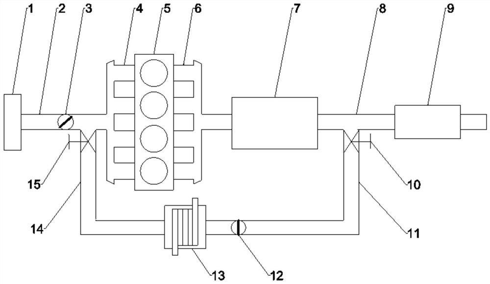
[0022] Please refer to figure 1 , figure 1 It is a schematic diagram of a specific embodiment of an engine system with an EGR pipeline provided by the present invention.
[0023] In this embodiment, the engine system specifically includes an air cleaner 1, an intake pipe 2, a throttle valve 3, an intake manifold 4, an engine body 5, an exhaust manifold 6, a three-way catalytic converter 7, an exhaust pipe 8, Muffler 9 , EGR intake pipe 11 , EGR valve 12 , EGR cooler 13 , EGR outlet pipe 14 .
[0024] The air cleaner 1, the intake pipe 2, the throttle valve 3, the intake manifold 4, the engine body 5, the exhaust manifold 6, the three-way catalytic converter 7, the exhaust pipe 8, and the muffler 9 are connected in sequence. O...
PUM
 Abstract
Description
Claims
Application Information
 - R&D
- Intellectual Property
- Life Sciences
- Materials
- Tech Scout
- Unparalleled Data Quality
- Higher Quality Content
- 60% Fewer Hallucinations
Browse by: Latest US Patents, China's latest patents, Technical Efficacy Thesaurus, Application Domain, Technology Topic, Popular Technical Reports.
© 2025 PatSnap. All rights reserved.Legal|Privacy policy|Modern Slavery Act Transparency Statement|Sitemap|About US| Contact US: help@patsnap.com


