
Inverter apparatus

A converter and frequency technology, applied in the field of converter devices, can solve problems such as insufficient status, reduce maintenance labor and costs, and prevent overcurrent

Inactive Publication Date: 2008-06-18
FUJI ELECTRIC CO LTD
View PDF2 Cites 4 Cited by
  • Summary
  • Abstract
  • Description
  • Claims
  • Application Information

AI Technical Summary

Problems solved by technology

[0012] However, in the converter device of this Patent Document 2, the maximum output voltage of the converter is limited by the ripple voltage included in the DC voltage of the DC intermediate circuit, and there arises a problem that the output voltage becomes insufficient in a region where the output voltage becomes high.

Method used


Image

  • Inverter apparatus
  • Inverter apparatus
  • Inverter apparatus

Examples


Embodiment Construction

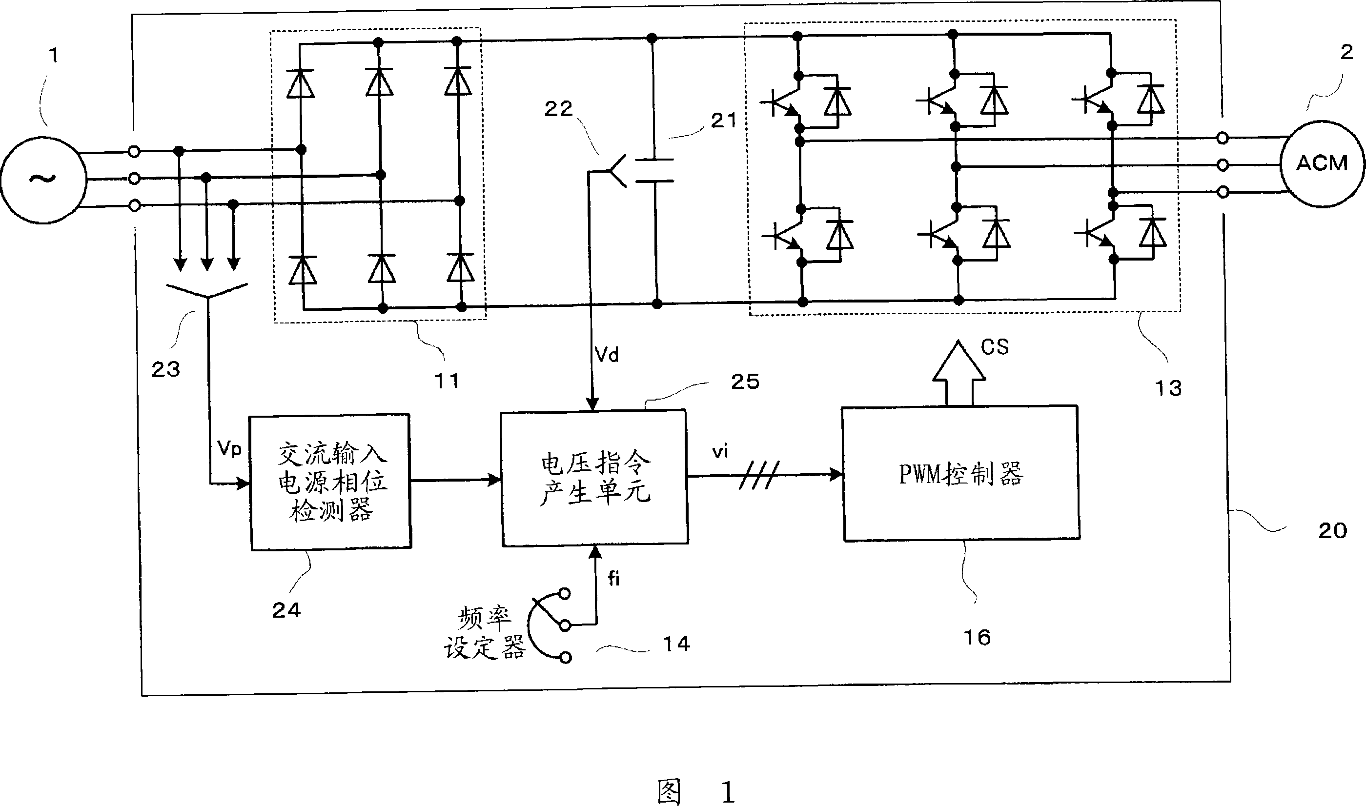
[0039] FIG. 1 is a circuit configuration diagram showing an inverter device according to a first embodiment of the present invention. In FIG. 1 , parts having the same functions as those of the conventional configuration shown in FIG. 9 are denoted by the same reference numerals and detailed description thereof will be omitted.

[0040] The inverter device 20 shown in FIG. 1 is provided with a film capacitor 21 whose capacity is smaller than that of the electrolytic capacitor 12 and whose main purpose is to absorb noise generated during the switching operation of the inverter circuit 13 instead of the electrolytic capacitor 12 shown in FIG. 9 . Therefore, the capacity of the smoothing capacitor is set to be small. Furthermore, a DC voltage detector 22 for detecting the voltage across the film capacitor 21, an AC voltage detector 23 for detecting the voltage of the AC input power supply 1, and a device for detecting the voltage phase based on the detection value of the AC volta...


PUM


Abstract

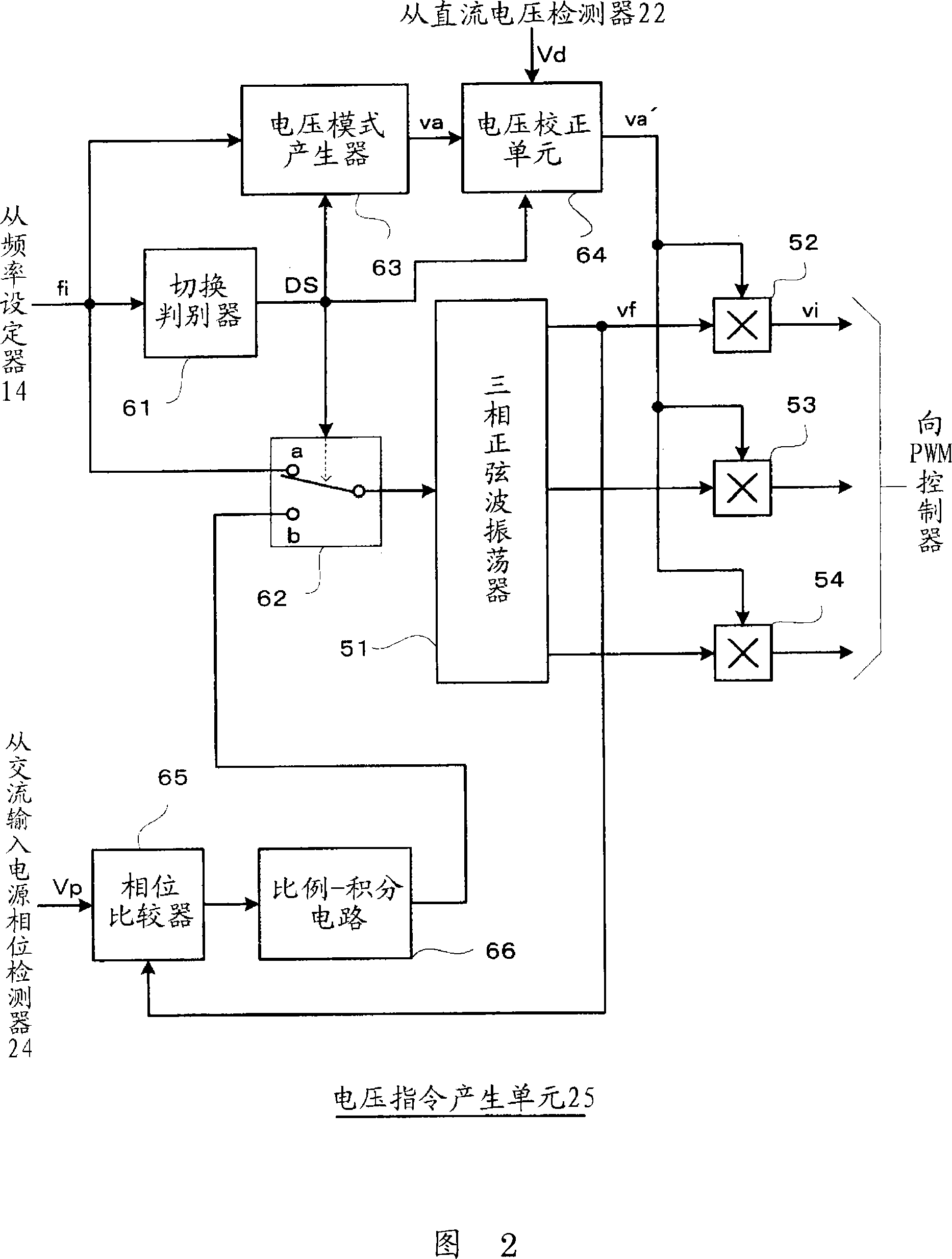
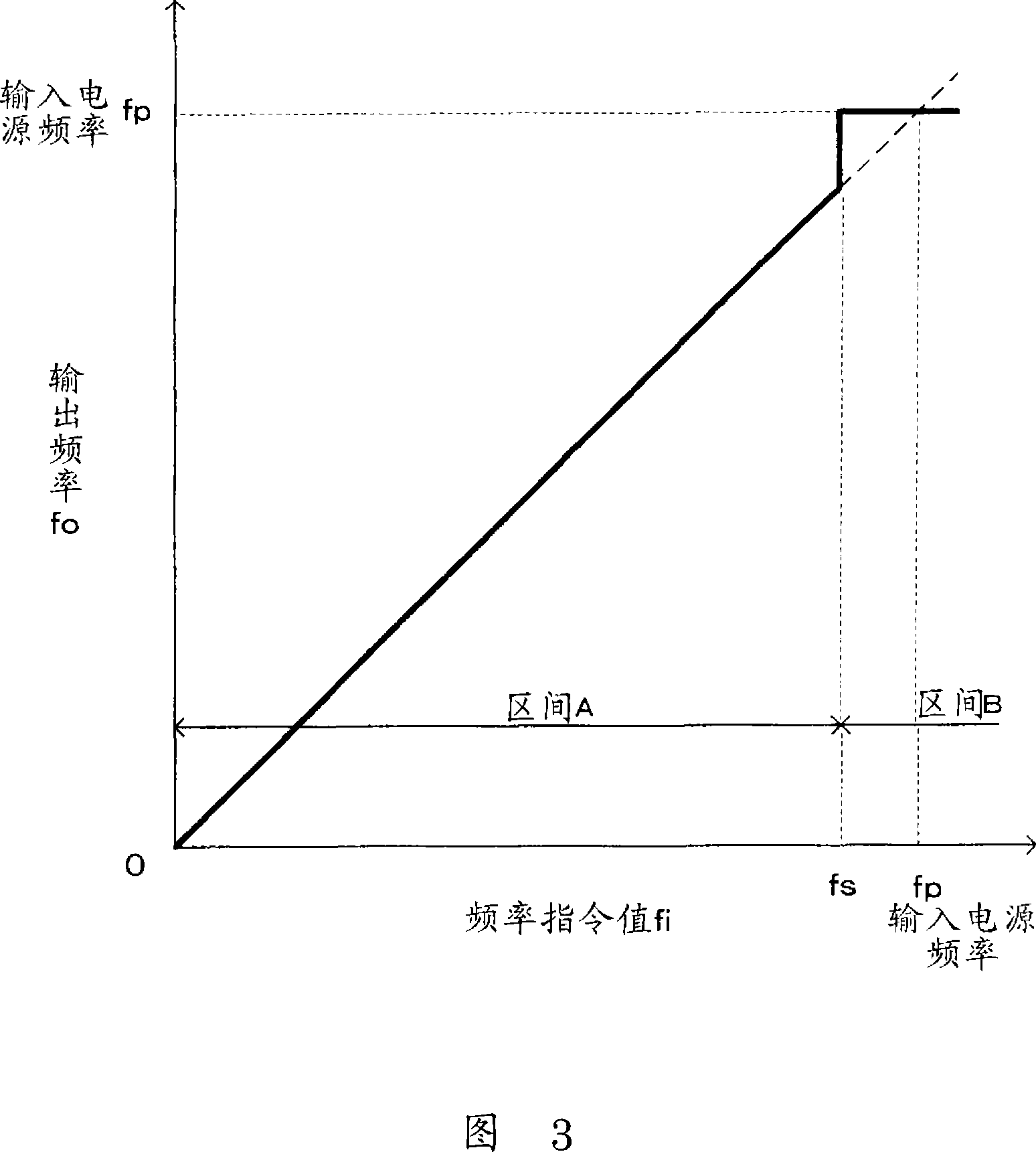
An inverter apparatus can lengthen a lift span and improve efficiency. Instead of a conventional electrolytic capacitor, only a noise absorption film capacitor is provided in a DC intermediate circuit between rectifying and inverter circuits. In a voltage command generating unit, when a frequency set by a frequency setting unit is within a predetermined range including the frequency of an AC input power supply, PLL control is performed to make the frequency set by an output voltage command signal equal to the frequency of the AC input power supply voltage, and to substantially synchronize the peak value of an output voltage from the inverter circuit with the peak value of a voltage formed between both ends of the film capacitor. Accordingly, output voltage amplitude is generated when the frequency set by the output voltage command signal equals the frequency of the voltage of the AC input power supply.

Description

technical field [0001] The invention relates to a converter device, which rectifies the three-phase AC voltage of an AC input power supply through a rectifier circuit, and converts the rectified voltage into The three-phase AC voltage of the desired frequency and amplitude is supplied to the load. Background technique [0002] FIG. 9 shows a circuit configuration diagram of a conventional converter device that converts a three-phase AC voltage from an AC input power source 1 such as a commercial power supply into a three-phase AC voltage of a desired frequency and supplies it to the AC load as a load. Motor 2. [0003] In the converter device 10 shown in FIG. 9 , reference numeral 11 is a rectification circuit configured by connecting diodes for rectifying the three-phase AC voltage of the AC input power source 1 in a three-phase bridge connection. Reference numeral 12 is a capacitor constituted by an electrolytic capacitor for smoothing the voltage rectified by the rectif...

Claims


Application Information

Patent Timeline
Patent Type & Authority Applications(China)
IPC IPC(8): H02M7/48H02M7/5387H02M7/5395
CPCH02M2001/0022H02M5/458H02M1/0022
Inventor 松本吉弘
Owner FUJI ELECTRIC CO LTD
Learn More