
A Concrete Construction Method for Rectangular Vertical Well Holes

A construction method and concrete technology, which is applied in artificial islands, water conservancy projects, infrastructure projects, etc., can solve problems such as high safety protection requirements, large material consumption, and slow construction progress, so as to achieve efficient and convenient construction and controllable quality , Construction safety and reliability

Active Publication Date: 2022-05-24
SINOHYRDO ENG BUREAU 3 CO LTD
View PDF8 Cites 0 Cited by
  • Summary
  • Abstract
  • Description
  • Claims
  • Application Information

AI Technical Summary

Problems solved by technology

During the construction of rectangular vertical wells, workers are affected by factors such as narrow working space and high safety protection requirements when setting up construction platforms, installing and dismantling formwork, and pouring concrete, which often lead to difficult operations, slow construction progress, and material consumption. In the existing vertical well hole concrete construction technology, the method of erecting scaffolding in the well hole is only suitable for shallow well holes, and there are more materials occupying pressure and low operating efficiency; winches are often used in mining projects Combining the method of hanging plate construction, but the operation is difficult and requires professional equipment; (foldable) overall lifting formwork is used more, but consider its own weight (not too heavy) and formwork support structure and operation method (the larger the section , the more complex the structure, the more troublesome the operation) and other factors, it is mostly used for the concrete construction of well holes with small cross-sections

Method used


Image

  • A Concrete Construction Method for Rectangular Vertical Well Holes
  • A Concrete Construction Method for Rectangular Vertical Well Holes
  • A Concrete Construction Method for Rectangular Vertical Well Holes

Examples


Embodiment Construction

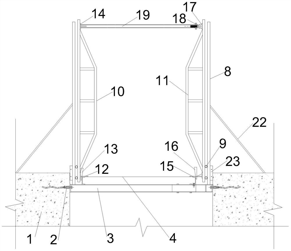
[0055] like Figure 1 to Figure 10 As shown, a concrete construction method for a rectangular vertical well hole of the present invention comprises the following steps:

[0056] Step 1, pouring the concrete foundation: according to the size of the rectangular vertical well hole, construct a concrete foundation 1 at the bottom of the shaft, and pre-embed multiple pairs of lower Doka formwork positioning cones 2 in the concrete foundation 1 along its length direction;

[0057] Step 2, hoisting the support structure: use the lifting equipment to hoist the support structure, and the support structure includes an operation platform 4 and a plurality of main beams 3 fixed on the bottom of the operation platform 4 and matched with multiple pairs of lower multi-card template positioning cones 2;

[0058] Step 3. Preliminary fixing of the bottom steel formwork: the bottom steel formwork 23 is clamped by the concrete foundation 1 and the purlin, and one side purlin along the length dire...


PUM


Abstract

The invention discloses a concrete construction method for a rectangular vertical shaft hole, comprising the steps of: 1. pouring the concrete foundation; 2. hoisting the support structure; Hole concrete; 6. Remove formwork support components; 7. Overall hoisting formwork support components and bracket structure; 8. Treat the upper Doka formwork positioning cone as the lower Doka formwork positioning cone, and cycle steps 3 to 7 to realize well hole concrete layered construction until the end of construction. The invention uses the bottom concrete foundation to support the main beam and the operating platform, uses the purlins to fix and support the concrete formwork, and then connects the bottom of the steel pipe bent frame at the fixed end and the steel pipe bent frame at the adjusting end to the operating platform to strengthen the fixing of the concrete formwork and realize The concrete construction of rectangular vertical well holes is instrumentalized, standardized and programmed, the overall structure is improved, the formwork is convenient to install and dismantle, the building materials can be reused, the construction is safe and reliable, and can be moderately adjusted.

Description

technical field [0001] The invention belongs to the technical field of rectangular vertical well hole concrete construction, in particular to a rectangular vertical well hole concrete construction method. Background technique [0002] In construction projects, rectangular vertical wells are often designed, such as vertical ventilation shafts in municipal pipe gallery projects, and similar vertical shaft structures formed between the water inlet of the dam and the partition wall of the trash rack. During the construction of rectangular vertical wells, when workers are working on construction platforms, formwork installation and dismantling, and concrete pouring, they are affected by factors such as narrow working space and high safety protection requirements, which often lead to difficult operations, slow construction progress, and material consumption. In the existing vertical well hole concrete construction technology, the method of erecting scaffolding in the well hole is ...

Claims


Application Information

Patent Timeline
Patent Type & Authority Patents(China)
IPC IPC(8): E02D29/12
CPCE02D29/12
Inventor 吴刚李东锋郑亚飞雷汉勋孙玉双许泾川赵正平张斌
Owner SINOHYRDO ENG BUREAU 3 CO LTD
Learn More