
Traveling wave tube clamping rod production die

A technology for clamping rods and traveling wave tubes, which is applied in the field of production molds for traveling wave tube clamping rods, can solve the problems of inability to improve mold shaping efficiency, inability to improve mold clamping processing, and inconvenient fixing of traveling wave tube clamps, etc., to achieve Improve the handling of flipping and loading, prevent the fixture from falling off, and improve the effect of fixture fixing

Pending Publication Date: 2021-08-27
温州南冠机械有限公司
View PDF0 Cites 0 Cited by
  • Summary
  • Abstract
  • Description
  • Claims
  • Application Information

AI Technical Summary

Problems solved by technology

[0004] The purpose of the present invention is to provide a production mold for the traveling wave tube clamping rod to solve the problem that the existing traveling wave tube clamping rod proposed in the above background technology is inconvenient to play a good role in the process of injection molding production and preparation of the traveling wave tube The fixture is fixed. When the two halves of the mold are placed, because the mold body is relatively heavy, the clamping process of the mold cannot be improved. During the use of the traditional mold, the molding efficiency of the mold cannot be improved, and the mold is easily demoulded. Problems causing unnecessary demoulding difficulties

Method used


Image

  • Traveling wave tube clamping rod production die
  • Traveling wave tube clamping rod production die
  • Traveling wave tube clamping rod production die

Examples


Embodiment Construction

[0024] The following will clearly and completely describe the technical solutions in the embodiments of the present invention with reference to the accompanying drawings in the embodiments of the present invention. Obviously, the described embodiments are only some, not all, embodiments of the present invention. Based on the embodiments of the present invention, all other embodiments obtained by persons of ordinary skill in the art without making creative efforts belong to the protection scope of the present invention.

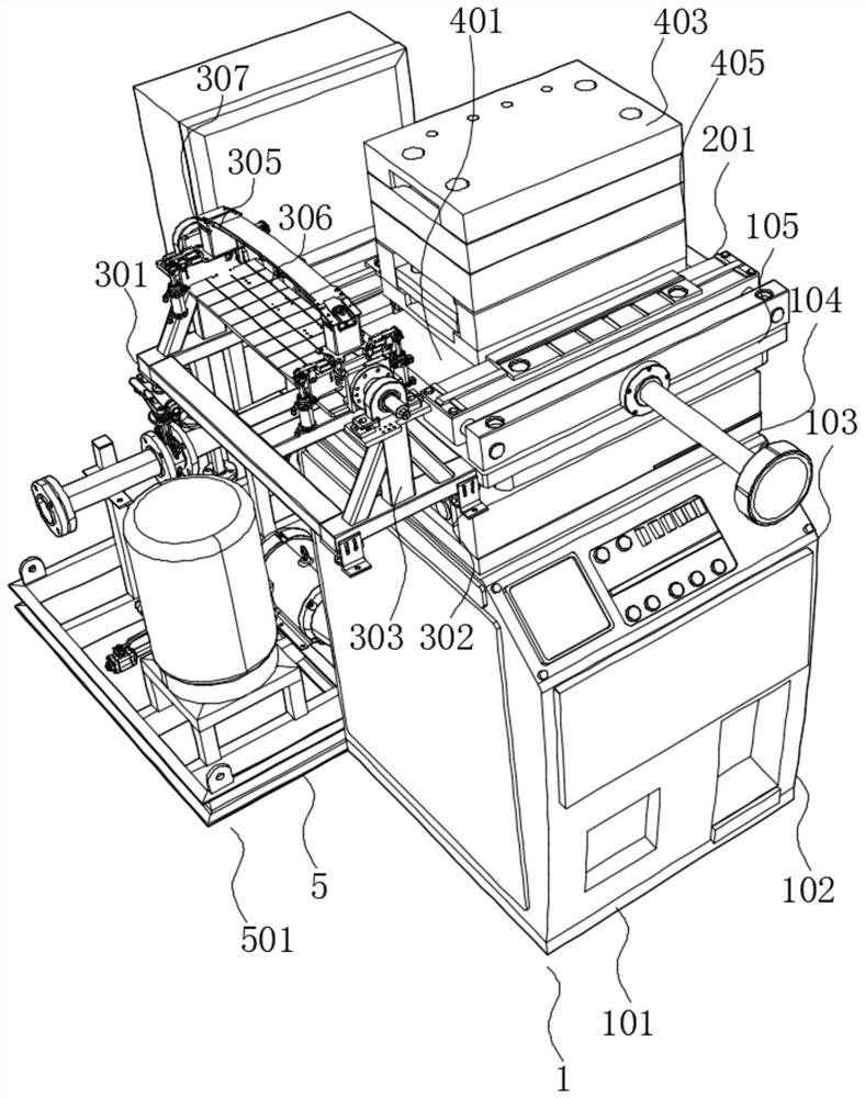
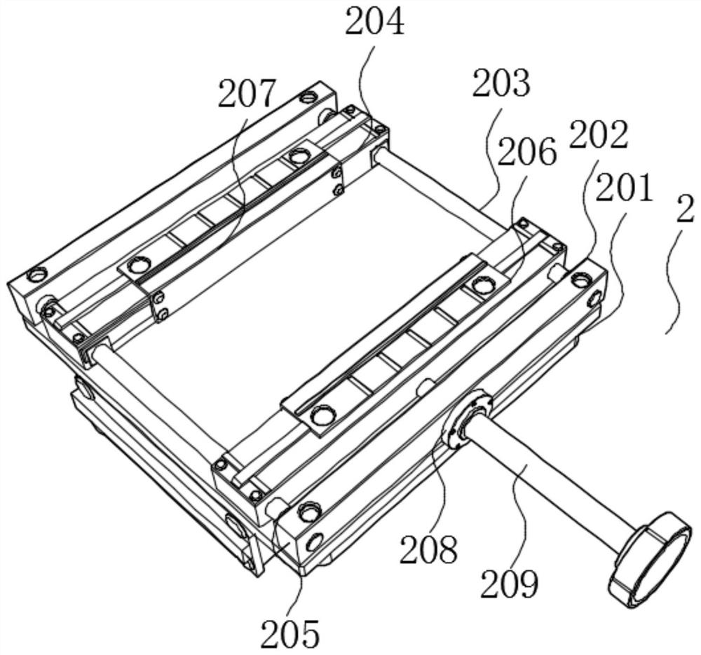
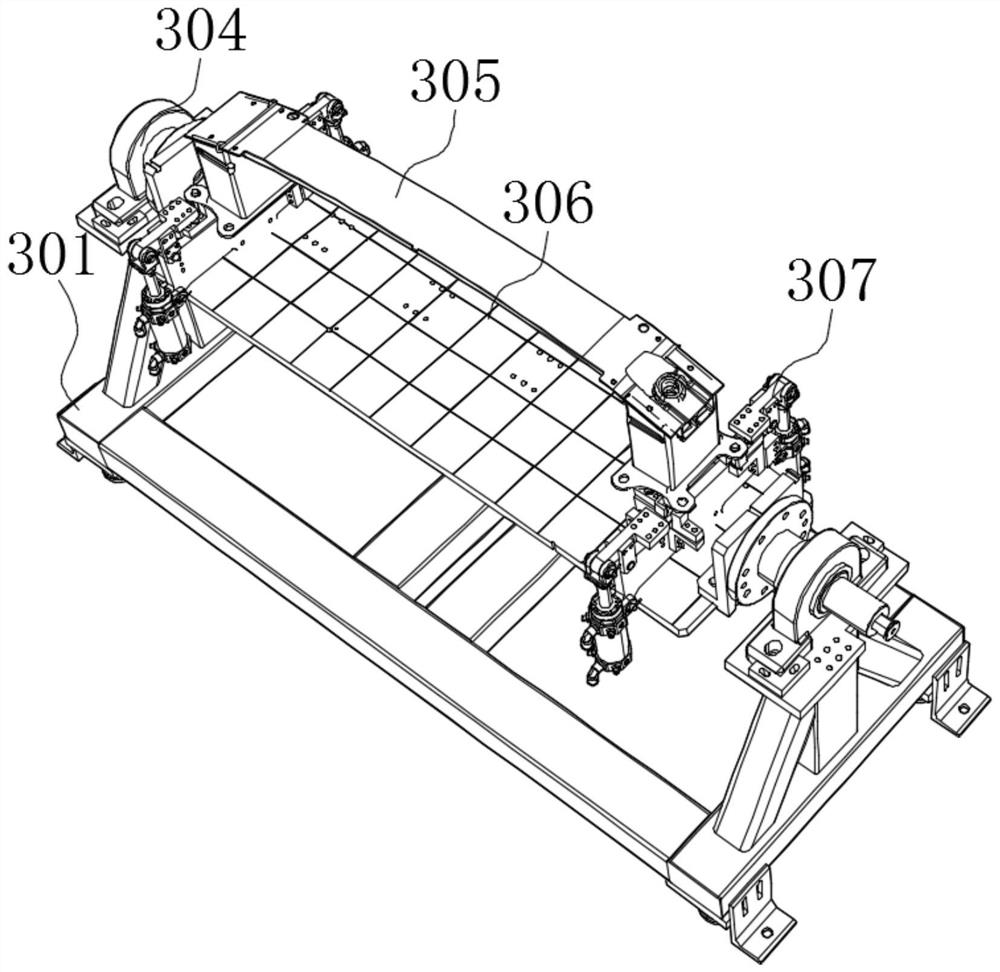
[0025] see Figure 1-5 , the present invention provides a technical solution: a traveling wave tube clamping rod production mold, including a fixture support mechanism 1, the fixture support mechanism 1 includes a support base 101 fixed to the ground support, the top middle of the support base 101 is fixedly supported and installed with Support the box body 102, the side wall surface of the support box body 102 is fixedly and inclinedly installed with a PLC co...


PUM


Abstract

The invention discloses a traveling wave tube clamping rod production die which comprises a clamp supporting mechanism. The clamp supporting mechanism comprises a supporting base supported and fixed to the ground, a supporting box body is fixedly supported and installed in the middle of the top end of the supporting base, and a PLC is fixedly and obliquely installed on the surface of the side wall of the supporting box body. Supporting pedestals are fixedly supported and installed in the middle of the top end of the supporting box body, connecting buckles are fixedly installed on the surfaces of the supporting pedestals, and damping supporting legs are fixedly supported and installed at the four corners of the bottom of the supporting base. According to the scheme, through the arrangement of the supporting base and the damping supporting legs, the die can be conveniently supported and fixed to the ground in the use process; and when the clamp clamping mechanism at the top runs, power transmitted by the top can play a good supporting and limiting role, displacement caused in the clamping process can be avoided, and the arranged supporting pedestals are convenient to install.

Description

technical field [0001] The invention relates to the field of mold technology, in particular to a production mold for a traveling wave tube clamping rod. Background technique [0002] Mold, various molds and tools used in industrial production for injection molding, blow molding, extrusion, die-casting or forging forming, smelting, stamping and other methods to obtain the required products. In short, a mold is a tool used to make shaped objects. This tool is composed of various parts, and different molds are composed of different parts. It mainly realizes the processing of the shape of the article through the change of the physical state of the formed material. Known as the "Mother of Industry". [0003] The existing traveling wave tube clamping rod is not convenient to fix the traveling wave tube as a good fixture in the process of injection molding production and preparation. When the two halves of the mold are placed, the clamping process of the mold cannot be improved d...

Claims


Application Information

Patent Timeline
Patent Type & Authority Applications(China)
IPC IPC(8): B29C45/03B29C45/17B29C45/46B29C45/74B29C45/76
CPCB29C45/03B29C45/1742B29C45/1744B29C45/1756B29C45/1761B29C45/46B29C45/74B29C45/76B29C2045/1765B29C2045/465B29C2045/7606
Inventor 李淑芹
Owner 温州南冠机械有限公司
Learn More