Fly-cutting trajectory planning method, fly-cutting control method and fly-cutting system

A trajectory planning and fly-cutting technology, which is applied in the field of component processing, can solve the problems of prolonging processing time and achieve the effects of saving processing time, reasonable path planning, and improving processing efficiency

Active Publication Date: 2021-08-24
ZHEJIANG RECI LASER TECH CO LTD
View PDF7 Cites 0 Cited by
  • Summary
  • Abstract
  • Description
  • Claims
  • Application Information

AI Technical Summary

Problems solved by technology

[0005] The first purpose of the present invention is to provide a flying cutting trajectory planning method to solve the technical problem of the laser cutting method in the prior art that the processing time is prolonged due to frequent lifting and lowering of the cutting head and acceleration and deceleration to a certain extent
[0006] The second purpose of the present invention is to provide a flying cutting control method to solve the technical problem of the laser cutting method in the prior art that the processing time is prolonged due to frequent lifting and lowering of the cutting head and acceleration and deceleration to a certain extent
[0007] The third purpose of the present invention is to provide a flying cutting system to solve the technical problem of the machine tool in the prior art that the processing time is prolonged due to frequent lifting and lowering of the cutting head and acceleration and deceleration to a certain extent

Method used


Image

  • Fly-cutting trajectory planning method, fly-cutting control method and fly-cutting system
  • Fly-cutting trajectory planning method, fly-cutting control method and fly-cutting system
  • Fly-cutting trajectory planning method, fly-cutting control method and fly-cutting system

Examples


Embodiment 1

[0069] The fly-cutting trajectory planning method provided in this embodiment is used to plan the final flying-cutting trajectory according to which the laser cutting head of the machine tool cuts the workpiece.

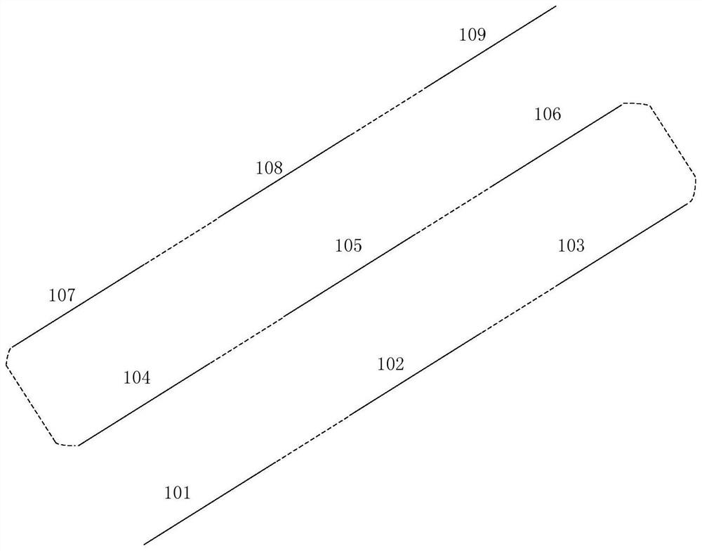
[0070] see Figure 1 to Figure 3 As shown, the fly-cut trajectory planning method provided in this embodiment includes the following steps:

[0071] Step S100, filtering out straight line trajectory segments from the primitives to be processed;

[0072] Step S110, grouping the filtered straight line trajectory segments according to whether they are collinear;

[0073] Step S120, forming at least one straight-line fly-cutting trajectory by sequentially connecting collinear straight-line trajectory segments through connecting straight lines;

[0074] Step S130, when there is one straight-line flying-cutting track, take the straight-line flying-cutting track as the final flying-cutting track; when there are multiple straight-line flying-cutting tracks, connect the adj...

Embodiment 2

[0147] Embodiment 2 provides a flying cutting control method. This embodiment controls the laser cutting head to cut the workpiece along the flying cutting trajectory planning method in Embodiment 1. The technical features of the flying cutting trajectory planning method disclosed in Embodiment 1 are also applicable. In this embodiment, the technical features of the fly-cut trajectory planning method disclosed in Embodiment 1 will not be described repeatedly.

[0148] The flying cutting control method provided in this embodiment controls the laser cutting head to cut the workpiece along the final flying cutting trajectory formed by the flying cutting trajectory planning method. The flying cutting control method includes the following steps:

[0149] When the laser cutting head corresponds to the straight segment track, control the laser cutting head to emit laser light;

[0150] When the laser knife corresponds to the connecting steering line or connecting straight line, contr...

Embodiment 3

[0153] The fly-cutting system provided in this embodiment includes a machine tool with a laser cutting head, a trajectory generating device and a control system.

[0154] The control system is electrically connected with the trajectory generating device and the machine tool respectively; the trajectory generating device can generate the final flying cutting trajectory according to the flying cutting trajectory planning method provided in the first embodiment; the control system can control the work of the machine tool according to the flying cutting control method provided in the second embodiment.


PUM


Abstract

The invention relates to the technical field of component machining, in particular to a fly-cutting trajectory planning method, a fly-cutting control method and a fly-cutting system. The fly-cutting trajectory planning method comprises the following steps of screening out linear trajectory segments from a to-be-processed primitive; grouping the screened linear track segments according to whether the linear track segments are collinear or not; sequentially connecting the collinear linear trajectory sections through connecting straight lines to form at least one linear fly-cutting trajectory; when the number of the linear fly-cutting trajectory is one, taking the linear fly-cutting trajectory as a final fly-cutting trajectory; and when the number of the linear fly-cutting trajectories is multiple, connecting the adjacent linear fly-cutting trajectories in a snakelike mode through the connecting steering lines, so that a final fly-cutting trajectory is formed. According to the fly-cutting control method, control is performed according to the final fly-cutting trajectory. The fly-cutting system adopts the fly-cutting control method for cutting. According to the fly-cutting trajectory planning method, the fly-cutting control method and the fly-cutting system, more reasonable path planning is provided for a cutting head through the final fly-cutting trajectory, the machining time is saved, and the machining efficiency is improved.

Description

technical field [0001] The invention relates to the technical field of component processing, in particular to a fly-cutting trajectory planning method, a fly-cutting control method and a fly-cutting system. Background technique [0002] Laser flying cutting is to use a high-power density laser beam to irradiate the material to be cut along the pre-planned flying cutting track, so that the material is quickly heated to the vaporization temperature, and evaporates to form holes. As the laser beam moves relative to the material, the holes continuously form width Very narrow kerf to complete the cutting of the material. [0003] In planar laser cutting, there are a large number of straight line segments to process part tracks. These straight line segments may be connected or may be far away. How to quickly complete the cutting of a large number of straight line segments to save processing time is a common problem. [0004] In the related art, the processing of laser cutting is ...

Claims


Application Information

Patent Timeline
IPC IPC(8): G05B19/19
CPCG05B19/19G05B2219/35321
Inventor 高林张长兴李晓屯
Owner ZHEJIANG RECI LASER TECH CO LTD
Why Eureka
Try Eureka