


Quick Research
Generate reliable direction feasibility study reports for your R&D in just a few steps.

Technical Q&A
Discover and master advanced knowledge NOW. Basics, ideas, possibilities, all at once.

Find Solutions
As an expert in R&D theories, this can generate solutions to your technical problems instantly.

Evaluate Feasibility
Analyze your overall solution with one click, know your potential R&D risks in advance.

Monitor Landscape
Get weekly tech updates, stay abreast of the latest tech innovations and key insights.
A method and device for finding a path
A path and path calculation technology, applied in the field of path finding, can solve problems such as large errors, and achieve the effects of accurate path selection, traffic balance, and reasonable path planning.
- Summary
- Abstract
- Description
- Claims
- Application Information
AI Technical Summary
Problems solved by technology
Method used
Image


Examples
Embodiment 1
[0053] In order to better illustrate the methods provided in the embodiments of the present application, the present application first introduces concepts that may be involved in the embodiments.
[0054] LBW (LinkBandWidth) is the allocatable bandwidth of the link. The basic configuration of the network is configured by the user according to the actual network conditions, and the link status of the border gateway is reported to the controller through the BGP-LS (Border Gateway Protocol Link-state) technology.
[0055] LCBW (LinkCurrentBandWidth) is the real-time bandwidth of the link. The LCBW can be collected actively by the controller or periodically reported to the controller by the network device.
[0056] LRBW (LinkReservedBandWidth) is the remaining allocable bandwidth of the link. The remaining allocable bandwidth of the link can be calculated by subtracting the real-time bandwidth of the link from the allocatable bandwidth of the link. LRBW can be calculated and mainta...
Embodiment 2
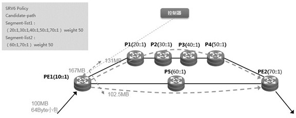
[0089] On the basis of the foregoing embodiments, this embodiment further introduces the pathfinding method in the foregoing embodiments in detail. In the method provided in this embodiment, with image 3 The network topology shown is taken as an example to further describe the above pathfinding method. Figure 5 shows a schematic flowchart of a pathfinding method provided by this embodiment, as shown in Figure 5 As shown, the method includes:
[0090] Step 201, obtaining the number of hops of the current node, the number of packets per unit time of user traffic flow, and the assignable bandwidth of the link;
[0091] Step 202, determining the path to be calculated;
[0092] Specifically, the path to be calculated may be determined according to step 2031 and step 2032 .
[0093] Of course, other ways can be used to determine the path to be calculated, for example, the inbound link of the current node can be determined, and so on. How to select and determine the path to b...
Embodiment 3
[0154] Because the number of encapsulated public network path label stacks is actually related to the number of nodes on the path to be calculated. In order to more accurately determine the remaining allocatable bandwidth of the link, in the method provided in this embodiment, the remaining allocatable bandwidth of the link determined in the foregoing embodiment is compensated.
[0155] For example, if image 3 As shown, when the user traffic reaches the starting node D, the public network path label stack will be encapsulated for the user traffic at the starting node. If the optimal path finally determined by the traffic is D->C->B->A, Then, three public network path label stacks carrying the addresses of nodes C, B, and A will be encapsulated for user traffic on the starting node D, that is, the actual size of the encapsulated user traffic should be: TempPaths[i] .THFBW=FBW+(56Byte+3 ×16Byte) ×FPC, but in the above-mentioned embodiment, when calculating the size of the enca...
PUM
 Abstract
Description
Claims
Application Information
 - R&D Engineer
- R&D Manager
- IP Professional
- Industry Leading Data Capabilities
- Powerful AI technology
- Patent DNA Extraction
Browse by: Latest US Patents, China's latest patents, Technical Efficacy Thesaurus, Application Domain, Technology Topic, Popular Technical Reports.
© 2024 PatSnap. All rights reserved.Legal|Privacy policy|Modern Slavery Act Transparency Statement|Sitemap|About US| Contact US: help@patsnap.com