Power supply circuit for cable comprehensive test

A technology of power supply circuit and comprehensive test, which is applied in the direction of high-efficiency power electronic conversion, measurement of resistance/reactance/impedance, components of electrical measuring instruments, etc., which can solve the problems of high commutation noise, poor high-voltage resistance, and poor operating efficiency of mechanical switches and other problems, to achieve the effect of good bidirectional withstand voltage performance, meet the detection requirements, and excellent insulation performance

Active Publication Date: 2021-08-24
GUANGDONG POWER GRID CO LTD +1
View PDF6 Cites 3 Cited by
  • Summary
  • Abstract
  • Description
  • Claims
  • Application Information

AI Technical Summary

Problems solved by technology

[0005] This application provides a power supply circuit for cable comprehensive test, which is used to solve the problem of high commutation noise of mechanical switches in existing topological circuits, poor high-voltage resistance performance, and low circuit integration, resulting in poor practical operation efficiency , and cannot meet the technical problems of comprehensive requirements for multiple state detection

Method used


Image

  • Power supply circuit for cable comprehensive test
  • Power supply circuit for cable comprehensive test
  • Power supply circuit for cable comprehensive test

Examples


Embodiment Construction

[0049] In order to enable those skilled in the art to better understand the solution of the present application, the technical solution in the embodiment of the application will be clearly and completely described below in conjunction with the accompanying drawings in the embodiment of the application. Obviously, the described embodiment is only It is a part of the embodiments of this application, not all of them. Based on the embodiments in this application, all other embodiments obtained by persons of ordinary skill in the art without making creative efforts belong to the scope of protection of this application.

[0050] The applicant found that the ultra-low frequency cosine square wave power supply can theoretically carry out withstand voltage, partial discharge and dielectric loss detection. Partial discharge and dielectric loss tests can be carried out when necessary.

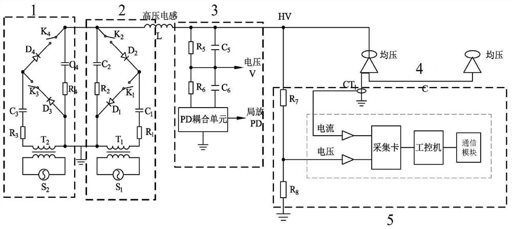
[0051] For ease of understanding, see figure 1 , an embodiment of a power supply circuit for a cable...


PUM


Abstract

The invention discloses a power supply circuit for a cable comprehensive test. The power supply circuit comprises a negative polarity high-voltage power supply circuit which comprises a first adjustable high-frequency alternating-current power supply, a first high-frequency high-voltage transformer, a first resistor group, a first capacitor group, a first light-operated semiconductor switch group and a first high-voltage silicon stack group; the positive polarity high-voltage power supply circuit comprises a second adjustable high-frequency alternating-current power supply, a second high-frequency high-voltage transformer, a second resistor group, a second capacitor group, a second light-operated semiconductor switch group and a second high-voltage silicon stack group; the voltage-dividing coupling unit comprises a third resistor group and a third capacitor group; the dielectric loss measuring unit comprises a divider resistor group, a current transformer, an acquisition card and an industrial personal computer; and the current transformer is electrically connected with one end of the cable to be detected. The technical problems that a mechanical switch in an existing topology circuit is large in reversing noise, poor in high-voltage resistance and low in circuit integration degree, consequently, the actual operation efficiency is poor, and the comprehensive requirement for detection of various states cannot be met can be solved.

Description

technical field [0001] The present application relates to the technical field of cable state detection, in particular to a power supply circuit for comprehensive cable tests. Background technique [0002] In recent years, distribution cables and related equipment have been gradually popularized and widely used in distribution networks, but frequent faults of distribution cables seriously affect the reliability of power supply. At this stage, there is no convenient, reliable and economical means of state detection for distribution cables. At present, the tests of distribution cables are mainly three types: withstand voltage test, partial discharge test and dielectric loss test. Each test corresponds to a professional equipment, and the integration level is not high. The on-site test takes a long time and is inconvenient to operate. [0003] Usually, the damped oscillatory wave power supply is mostly used for on-site partial discharge tests, which cannot meet the requirements...

Claims


Application Information

Patent Timeline
Patent Type & Authority Applications(China)
IPC IPC(8): G01R31/08G01R31/12G01R31/58G01R27/26G01R1/28
CPCG01R31/083G01R31/1272G01R27/2694G01R31/58G01R1/28Y02B70/10
Inventor 雷小月孙廷玺孔德武崔江静方义治刘颖郑柒拾张宽锋杨宇炎姜志彬赵尊慧蔡蔚梁育雄
Owner GUANGDONG POWER GRID CO LTD
Why Eureka
Try Eureka