Highway engineering supervision and inspection equipment
A technology for inspection equipment and supervision, which is applied in the field of highway inspection and acceptance, can solve problems such as inability to take pictures, long cycle time, and reduced detection accuracy, and achieve the effect of facilitating subsequent rectification
- Summary
- Abstract
- Description
- Claims
- Application Information
AI Technical Summary
Problems solved by technology
Method used
Image
Examples
Embodiment 1
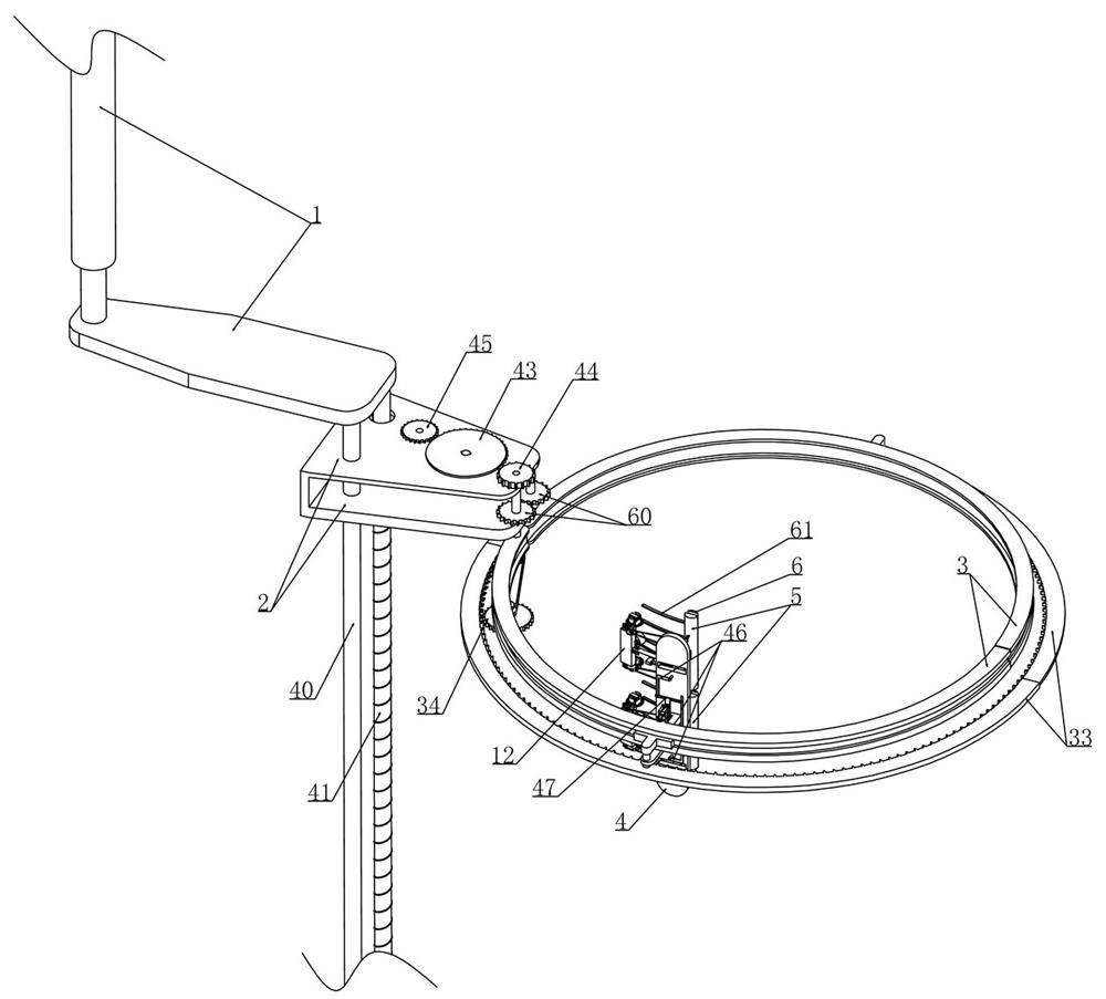
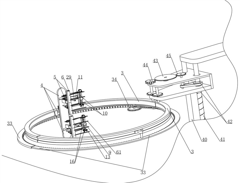
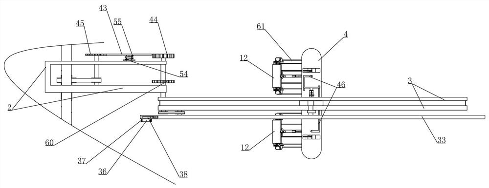
[0041] Embodiment 1. This embodiment provides a highway engineering supervision and inspection equipment, including a measuring vehicle and a mechanical wall is provided on the measuring vehicle. When this device is used in practice, that is, the inspection and acceptance personnel drive the measuring vehicle to drive the bridge surface road to be tested. and move the device to below the bridge deck road by operating the mechanical arm 1 located on the measuring car (moving the position of the measuring car so that the two semicircular guide rails 3 extending under the bridge deck road correspond to the pier position, that is, Make the center of the bridge pier coincide with the center of the circle formed by the two semicircular guide rails 3, the measuring vehicle and the mechanical arm 1 are not shown in the figure, and the mechanical arm 1 only shows part of the structure. Those skilled in the art can make corresponding improvements on the basis of this solution as needed, ...
Embodiment 2
[0050] Embodiment 2, on the basis of embodiment 1, as attached Figure 7 As shown, slide rails 12 are fixed at vertical intervals on the detection frame 4 and the camera 9 is vertically slidably installed in the slide rail 12. The lifting drive device includes an outer ring gear 13 that is rotatably installed at the upper and lower ends of the slide rail 12, as shown in the attached Figure 11 As shown, the outer ring gear 13 is coaxially fixed with two symmetrically arranged lifting plates 14, as attached Figure 12 As shown, the outer ring gear 13 is meshed with a transmission gear 15 rotatably mounted on the slide rail 12 and the transmission gear 15 is connected to the energy storage device, and the movement of the detection plate 6 causes the corresponding energy storage device to store energy. When the T-shaped plate 5 has not moved, the camera 9 is always positioned by the positioning device. Only when the bulge is larger and has exceeded the acceptance standard, the T-...
Embodiment 3
[0055] Embodiment 3, on the basis of embodiment 2, with reference to appended Figure 13 As shown, the energy storage device includes an energy storage gear 19 that is coaxially arranged with the transmission gear 15 and is rotatably mounted on the slide rail 12, as shown in the attached Figure 11 As shown, when the detection plate 6 moves along the corresponding T-shaped plate 5 to the point where it cannot continue to move, the energy storage rod 24 installed in rotation with it drives the cam plate 23 to rotate during its movement, and the cam plate 23 The rotation drives the tension pulley group 22 to move and then drives the transition gear 21 to rotate, and the rotation of the transition gear 21 drives the energy storage gear 19 to rotate and makes the energy storage spring 20 store energy (when the T-shaped plate 5 has not started to move , the camera 9 is in a positioned state and cannot be moved), so that when the positioning device releases the positioning of the ca...
PUM
 Abstract
Description
Claims
Application Information
 - R&D
- Intellectual Property
- Life Sciences
- Materials
- Tech Scout
- Unparalleled Data Quality
- Higher Quality Content
- 60% Fewer Hallucinations
Browse by: Latest US Patents, China's latest patents, Technical Efficacy Thesaurus, Application Domain, Technology Topic, Popular Technical Reports.
© 2025 PatSnap. All rights reserved.Legal|Privacy policy|Modern Slavery Act Transparency Statement|Sitemap|About US| Contact US: help@patsnap.com


