
Cleaning structure and laser processing equipment

A clean structure and clean technology, used in laser welding equipment, metal processing equipment, welding equipment and other directions, can solve the problems of inconvenient assembly and increased floor space, and achieve the effect of convenient assembly and compact overall structure

Inactive Publication Date: 2021-08-24
HANS LASER TECH IND GRP CO LTD
View PDF7 Cites 0 Cited by
  • Summary
  • Abstract
  • Description
  • Claims
  • Application Information

AI Technical Summary

Problems solved by technology

[0003] Based on this, it is necessary to provide a cleaning structure for the technical problems of inconvenient assembly and increased floor space when cleaning the existing boards.

Method used


Image

  • Cleaning structure and laser processing equipment
  • Cleaning structure and laser processing equipment
  • Cleaning structure and laser processing equipment

Examples


Embodiment Construction

[0032] In order to make the above objects, features and advantages of the present invention more comprehensible, specific implementations of the present invention will be described in detail below in conjunction with the accompanying drawings. In the following description, numerous specific details are set forth in order to provide a thorough understanding of the present invention. However, the present invention can be implemented in many other ways different from those described here, and those skilled in the art can make similar improvements without departing from the connotation of the present invention, so the present invention is not limited by the specific embodiments disclosed below.

[0033] In describing the present invention, it should be understood that the terms "center", "longitudinal", "transverse", "length", "width", "thickness", "upper", "lower", "front", " Back", "Left", "Right", "Vertical", "Horizontal", "Top", "Bottom", "Inner", "Outer", "Clockwise", "Counte...


PUM


Abstract

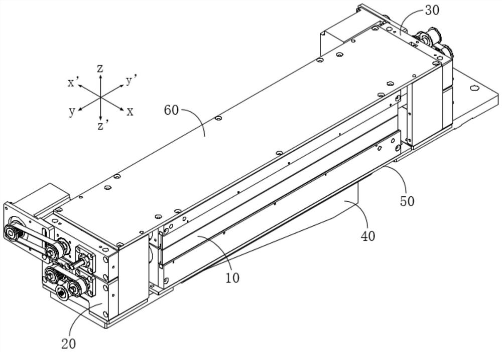
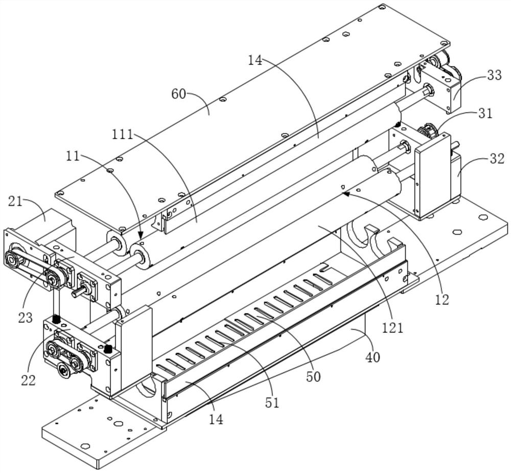
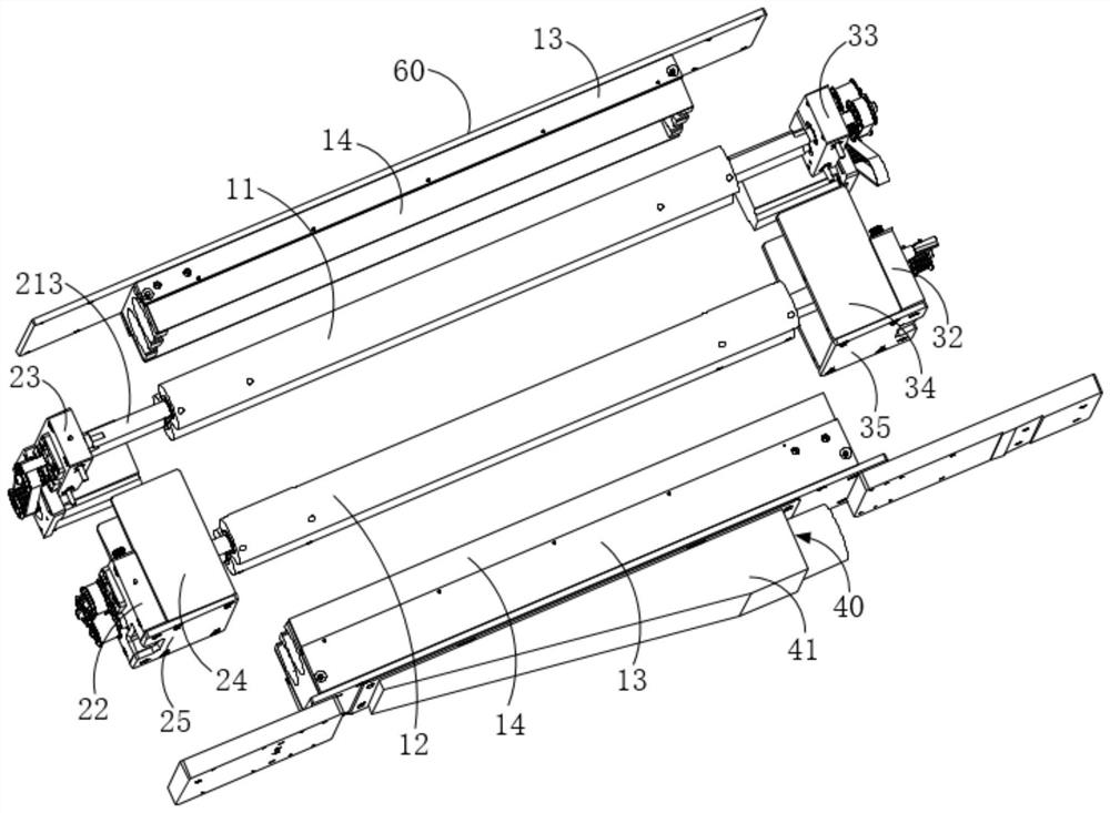
The invention relates to a cleaning structure and laser processing equipment. The cleaning structure comprises a rolling brush mechanism, a front end cover mechanism and a rear end cover mechanism. The rolling brush mechanism comprises a first rolling brush set and a second rolling brush set, the first rolling brush set and the second rolling brush set are oppositely arranged in a spaced manner in the first direction, and a first cleaning gap is formed between the first rolling brush set and the second rolling brush set. The front end cover mechanism is arranged at the first end, in the second direction, of the rolling brush mechanism, and the front end cover mechanism comprises a first driving set used for driving one of the first rolling brush set and the second rolling brush set to rotate. The rear end cover mechanism is arranged at the second end, in the second direction, of the rolling brush mechanism, and the rear end cover mechanism comprises a second driving set used for driving the other one of the first rolling brush set and the second rolling brush set to rotate. The cleaning structure provided by the invention can be directly arranged in a conveying mechanism used for conveying plates in a laser processing assembly line, so that the plates are conveyed to the position between the two rolling brush sets through the conveying mechanism, the assembly is convenient to carry out, and no extra floor space is needed.

Description

technical field [0001] The invention relates to the technical field of laser processing, in particular to a cleaning structure and laser processing equipment. Background technique [0002] After the plate is laser cut or marked, the processed plate needs to be sent to the cleaning module for plate cleaning, so as to ensure that the plate has a good processing effect. However, the size of the commonly used plate cleaning module is too large to be installed in the pre-assembled laser processing line, and even if it is installed, the size of the equipment will be affected, resulting in an increase in the area occupied by the equipment. At the same time, due to the limitation of the size of the given site, the laser processing equipment with added cleaning function will not be able to be inserted into the processing line. Contents of the invention [0003] Based on this, it is necessary to provide a cleaning structure to solve the technical problems of inconvenient assembly a...

Claims


Application Information

Patent Timeline
IPC IPC(8): B08B1/02B08B13/00B23K26/00
CPCB08B13/00B23K26/00B08B1/20B08B1/12
Inventor 邵雨化张忍李志伟王树蔚任晓融杨俊李仁博郑辉松张帅锋谢圣君吕启涛高云峰
Owner HANS LASER TECH IND GRP CO LTD
Learn More