
High-strain creep-fatigue coupling test method for material in low-temperature corrosion environment

A technology of low temperature corrosion and test method, which is applied in analyzing materials, testing material strength by applying stable tension/pressure, and testing material strength by applying repetitive force/pulse force, etc. It can solve the problem that the temperature control torque effect is difficult to eliminate and the system is stable for a long time. issues of sex

Pending Publication Date: 2021-08-20
725TH RES INST OF CHINA SHIPBUILDING INDAL CORP
View PDF0 Cites 3 Cited by
  • Summary
  • Abstract
  • Description
  • Claims
  • Application Information

AI Technical Summary

Problems solved by technology

[0004] In order to realize the evaluation of the service performance of structural materials in deep-sea complex working conditions, GB / T 20120.1-2006 "Metals and Alloys Corrosion-Corrosion Fatigue Test Part 1: Cycle Failure Test" and GB / T 2039-2012 "Metallic Materials Based on the standard of "Uniaxial Tensile Creep Test Method", the invention provides a material high strain creep-fatigue coupling test method in a low temperature corrosion environment. Solution environment maintenance, torque effect generated during fatigue test is difficult to eliminate, strain measurement and long-term stability of the whole system, realizing the performance test of high strain creep-fatigue coupling test of materials in low temperature corrosion environment

Method used


Image

  • High-strain creep-fatigue coupling test method for material in low-temperature corrosion environment
  • High-strain creep-fatigue coupling test method for material in low-temperature corrosion environment
  • High-strain creep-fatigue coupling test method for material in low-temperature corrosion environment

Examples


Embodiment 1

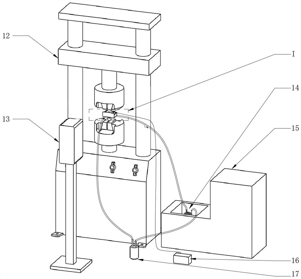
[0045] Titanium alloy high strain creep-fatigue coupling test method under low temperature corrosion environment, described high strain creep-fatigue coupling test device includes a fatigue testing machine 12, a low temperature instrument 15, a video extensometer 13, a submersible pump, A corrosion solution container 17, a multi-layer spiral pipe 14, a box-shaped corrosion tank and a pair of upper and lower clamping rods that can be relatively arranged and clamped on the fatigue testing machine 12;

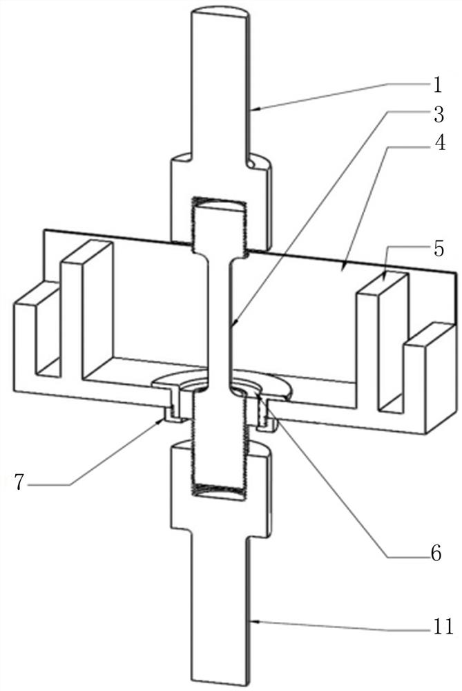
[0046] Both the upper clamping rod 1 and the lower clamping rod 11 are provided with cylindrical grooves capable of matching the metal sample 3;

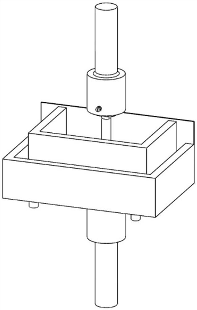
[0047] The front wall of the box-shaped corrosion tank adopts a test plate 4 that can be used in conjunction with the video extensometer 13. The box-shaped corrosion tank is provided with a U-shaped overflow plate 5 that is fixedly connected to the test plate 4. The U-shaped overflow plate The two parallel surfaces of the plate 5 are pa...


PUM


Abstract

The invention discloses a high-strain creep-fatigue coupling test method for a material in a low temperature corrosion environment. The test is carried out by means of a test device, and the test device comprises a fatigue tester, a low temperature instrument, a video extensometer, a corrosion solution container, a submersible pump arranged in the corrosion solution container, a multilayer spiral pipe, a box-shaped corrosion tank, an upper clamping rod and a lower clamping rod; the space in the box-shaped corrosion tank is divided into a cuboid chamber and a U-shaped chamber through a U-shaped overflow plate, the bottom wall of the cuboid chamber is provided with a through hole and a liquid inlet hole through which a metal sample passes, the bottom wall of the U-shaped chamber is provided with a liquid outlet hole which can be connected with a corrosion solution container through a conduit, and a multi-layer spiral pipe in the low-temperature instrument is respectively connected with the liquid inlet hole and the submersible pump; and after the test device is assembled, a metal sample is tightly connected into the box-shaped corrosion tank, and then the test can be carried out. The test method provided by the invention meets the test requirements of a high-strain fatigue creep test in a low-temperature corrosion environment, and corrosion fatigue creep tests at different temperatures can be realized.

Description

technical field [0001] The invention relates to the technical field of material high-strain creep-fatigue coupling testing, in particular to a material high-strain creep-fatigue coupling testing method in a low-temperature corrosion environment. Background technique [0002] Creep test and fatigue test are important methods for material safety evaluation. In order to evaluate the service performance of structural materials in deep sea complex environment, it is necessary to carry out tests on high strain fatigue and creep performance of materials in low temperature corrosion environment. At present, there are few studies on fatigue-creep coupled loading in low-temperature corrosion environment at home and abroad, and no relevant professional test equipment has been found. Fatigue-creep coupled loading in a low-temperature corrosion environment has the following difficulties: low-temperature long-term tests are generally realized through a low-temperature environmental chambe...

Claims


Application Information

Patent Timeline
Patent Type & Authority Applications(China)
IPC IPC(8): G01N3/02G01N3/18G01N3/32G01N3/06
CPCG01N3/02G01N3/18G01N3/32G01N3/068G01N2203/0003G01N2203/0005G01N2203/0017G01N2203/0071G01N2203/0073G01N2203/0228G01N2203/024G01N2203/0641Y02E30/30
Inventor 王磊徐魁龙杜卓同
Owner 725TH RES INST OF CHINA SHIPBUILDING INDAL CORP
Learn More