
Rapid drying device for stainless steel machining process

A processing and rapid drying technology, applied in drying, drying machine, drying gas arrangement, etc., can solve problems such as uneven heating, low drying efficiency, and influence on workpiece structure, so as to facilitate the reciprocating heating cycle and ensure Drying effect, no flow loss effect

Inactive Publication Date: 2021-08-20
江苏鑫泽不锈钢制品有限公司
View PDF5 Cites 3 Cited by
  • Summary
  • Abstract
  • Description
  • Claims
  • Application Information

AI Technical Summary

Problems solved by technology

[0003] However, the current rapid drying device used in stainless steel processing often suffers from uneven heating and low drying efficiency, and the air circulation inside the drying device is not good, and it is easy to inhale a large amount of dust during the air intake process. , affecting the drying effect. At the same time, when the stainless steel workpiece is sent into the device, because the specific position of the workpiece cannot be controlled, it is easy to cause damage to the drying equipment in the device, and it will also affect the structure of the workpiece.

Method used


Image

  • Rapid drying device for stainless steel machining process
  • Rapid drying device for stainless steel machining process
  • Rapid drying device for stainless steel machining process

Examples


Embodiment Construction

[0022] Next, the technical solutions in the embodiments of the present invention will be apparent from the embodiment of the present invention, and it is clearly described, and it is understood that the described embodiments are merely embodiments of the present invention, not all of the embodiments. Based on the embodiments of the present invention, there are all other embodiments obtained without making creative labor without making creative labor premises.

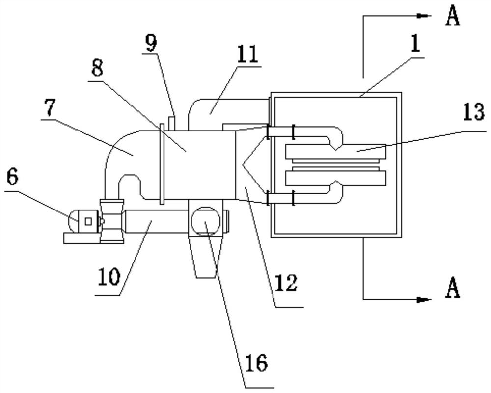
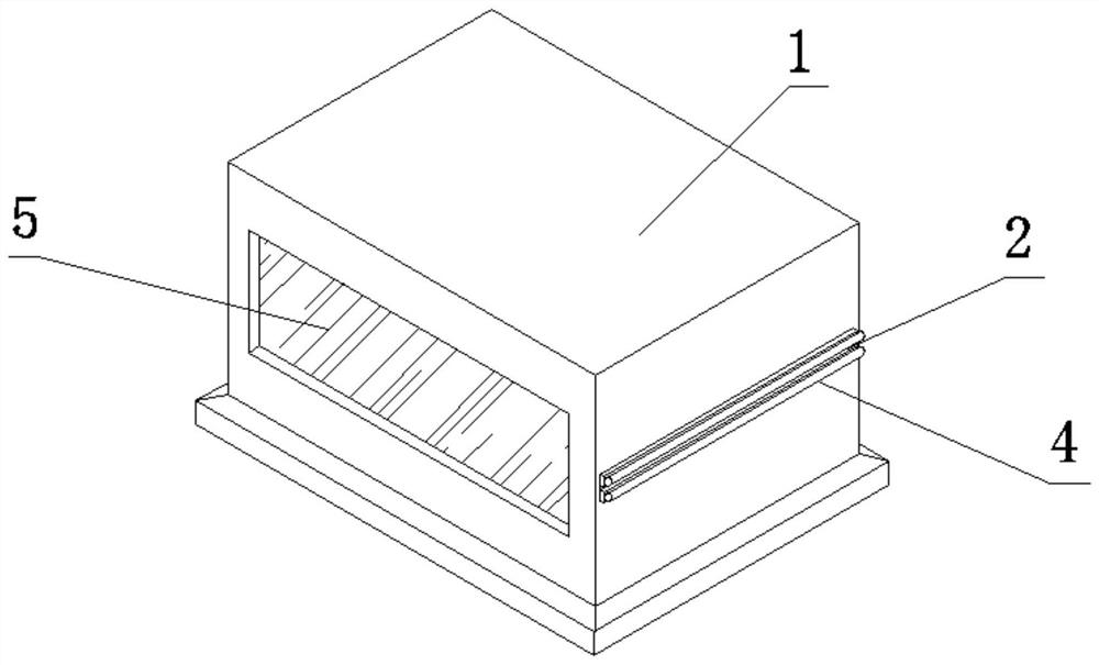
[0023] See Figure 1-3 The present invention provides a technical solution for a rapid drying device for stainless steel processing processes:

[0024] A fast drying apparatus for stainless steel processing process, including a box body 1, and a feed port 2 and a discharge port 3 are respectively fixed, respectively, and the feed port 2 and discharge ports. The upper and lower ends of the mouth 3 are fixedly provided with a support plate 14, and the support plate 14 is fixedly mounted having a first roller 4, and a visible w...


PUM


Abstract

The invention discloses a rapid drying device for the stainless steel machining process. The rapid drying device comprises a box body, a feeding port and a discharging port are fixedly formed in the middles of the left side and the right side of the box body correspondingly, supporting plates are fixedly arranged at the upper ends and the lower ends of the feeding port and the discharging port correspondingly, and first carrier rollers are fixedly installed outside the supporting plates; and a visual window is fixedly arranged in the middle of the front end of the box body, second carrier rollers are movably installed in the middle of the interior of the box body, drying air knives are fixedly installed at the rear ends of the second carrier rollers, the drying air knives are fixedly connected to a forked air duct, and a heat exchanger is fixedly connected to the left end of the forked air duct. When the rapid drying device is used, a stainless steel band is firstly put into the box body from the feeding port, under the action of the first carrier rollers, the plate band is preliminarily positioned, a draught fan is started, the plate band is gradually and completely fed into the box body, the plate band sequentially penetrates through the four sets of second carrier rollers, the drying air knives blow air from the position above the plate band and the position below the plate band, and all-directional drying of the stainless steel band is effectively guaranteed.

Description

Technical field [0001] The present invention relates to the art of stainless steel processing, and is specifically a fast drying device for a stainless steel machining process. Background technique [0002] Dryer can be divided into two industrial and civilian, industrial dryers are also called drying equipment or dryers, and civil dryers are one of the washing machines. It is generally used to remove clothing and other textiles after water washing. Water. Dryer has several modes of tape drying, roller drying, box drying, tower drying, etc. The heat source is coal, electricity, gas, etc .; material is hot and air flow and radiation type during drying. The hot air drum drying is a hot air flow to move forward from the tail, sufficiently exposed to the material, through heat transfer, convection, radiation heat transfer, direct delivery to the material, so that the material of the material is constantly evaporated in the cylinder, The venting device of the mouth takes a large amoun...

Claims


Application Information

Patent Timeline
Patent Type & Authority Applications(China)
IPC IPC(8): F26B15/12F26B21/00F26B25/12F26B25/20
CPCF26B15/12F26B21/002F26B25/12F26B25/20
Inventor 宋清宋浩宋洁
Owner 江苏鑫泽不锈钢制品有限公司
Learn More