
Precise small part smoothing device

A precise and smooth technology, used in surface polishing machine tools, grinding/polishing equipment, machine tools suitable for grinding workpiece edges, etc., can solve problems such as low efficiency and large footprint

Active Publication Date: 2021-08-20
杭州临安华滢精密元件有限公司
View PDF13 Cites 0 Cited by
  • Summary
  • Abstract
  • Description
  • Claims
  • Application Information

AI Technical Summary

Problems solved by technology

[0002] Compared with the grinding and polishing process of the dry-type smoothing machine, the process of the dry-type smoothing machine is relatively simple, with high work efficiency, consistent mirror effect of the processed workpiece, good working environment, low requirements for workers' proficiency, and reduced labor intensity of workers. , low cost and other advantages, the dry polishing machine needs a large amount of smoothing sand, and the parts to be polished are rotated in the smoothing sand to achieve polishing. The disadvantage is that the equipment occupies a large space, requires a large amount of smoothing sand, and has low efficiency.

Method used


Image

  • Precise small part smoothing device
  • Precise small part smoothing device
  • Precise small part smoothing device

Examples


specific Embodiment approach 1

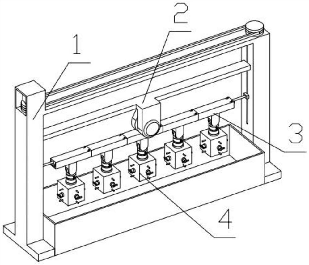
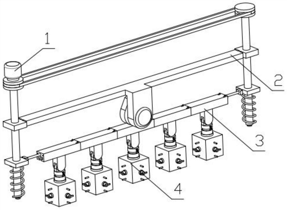
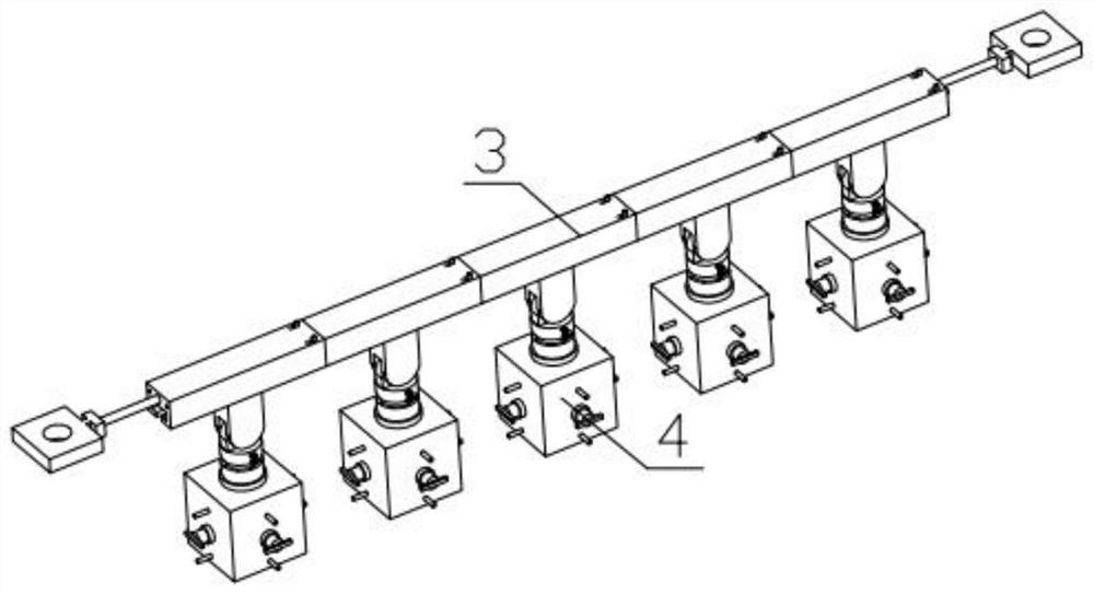
[0033] Combine below Figure 1-15 Describe this embodiment, a precise light sliding device for small pieces, including a device lifting mechanism 1, an up and down streamer mechanism 2, a combined connection mechanism 3 and a precise streamer mechanism 4, the upper and lower streamer mechanisms 2 are slidably installed on the device lifting mechanism 1 In the groove of the device, the device lifting mechanism 1 is threadedly connected with the upper and lower streamer mechanisms 2, the combined connecting mechanism 3 is fixedly installed on the device lifting mechanism 1, and the combined connecting mechanism 3 and the precise streamer mechanism 4 are hinged.

specific Embodiment approach 2

[0035] Combine below Figure 1-15Describe this embodiment, this embodiment will further explain the second embodiment, the device lifting mechanism 1 includes a bottom box 1-1, a U-shaped frame 1-2, a lifting motor 1-3, a sprocket 1-4, a chain 1-5, lifting threaded rod 1-6, supporting spring 1-7, the bottom box 1-1 is fixedly installed on the U-shaped frame 1-2, the lifting motor 1-3 is fixedly installed on the U-shaped frame 1-2, and the lifting The output end of the motor 1-3 is fixedly equipped with a sprocket 1-4, the sprocket 1-4 is meshed with the chain 1-5, the sprocket 1-4 is fixedly connected with the lifting threaded rod 1-6, and the lifting threaded rod 1-6 The rotation is installed in the groove provided on the U-shaped frame 1-2, and the support spring 1-7 is fixedly installed on the U-shaped frame 1-2.

specific Embodiment approach 3

[0037] Combine below Figure 1-15 Describe this embodiment, this embodiment will further explain the first embodiment, the upper and lower streamer mechanism 2 includes a lifting beam plate 2-1, a toggle motor 2-2, a cam 2-3, and the lifting beam plate 2-1 is fixed A toggle motor 2-2 is installed, and the output end of the toggle motor 2-2 is fixedly equipped with a cam 2-3, and the lift beam plate 2-1 is slidably installed in the groove provided on the U-shaped frame 1-2, and the lift beam Plate 2-1 is threadedly connected with lifting threaded rod 1-6.


PUM


Abstract

The invention relates to a polishing device, in particular to a precise small part smoothing device which comprises a device lifting mechanism, an up-down smoothing mechanism, a combined connecting mechanism and precise smoothing mechanisms. The up-down smoothing mechanism is slidably mounted in a groove formed in the device lifting mechanism, the device lifting mechanism is in threaded connection with the up-down smoothing mechanism, and the combined connecting mechanism is fixedly mounted on the device lifting mechanism and is in hinged connection with the precise smoothing mechanisms. The device can independently polish small parts, is high in polishing efficiency and speed, can perform polishing in different motion trails according to shapes, and has the function of independently polishing large parts.

Description

technical field [0001] The invention relates to a polishing device, in particular to a precision small piece polishing device. Background technique [0002] Compared with the grinding and polishing process of the dry-type smoothing machine, the process of the dry-type smoothing machine is relatively simple, with high work efficiency, consistent mirror effect of the processed workpiece, good working environment, low requirements for workers' proficiency, and reduced labor intensity of workers. , low cost and other advantages, the dry polishing machine requires a large amount of smoothing sand, and the parts to be polished are rotated in the smoothing sand to achieve polishing. The disadvantage is that the equipment occupies a large space, requires a large amount of smoothing sand, and has low efficiency. Contents of the invention [0003] The main technical problem to be solved by the present invention is to provide a precise polishing device for small pieces. This device c...

Claims


Application Information

Patent Timeline
IPC IPC(8): B24B31/02B24B31/12B24B31/14
CPCB24B31/02B24B31/12B24B31/14
Inventor 刘利峰
Owner 杭州临安华滢精密元件有限公司
Learn More