optical lens
An optical lens and lens technology, applied in the field of optical lenses, can solve the problems of difficult ultra-high pixels, light and thin optical lenses, etc., to achieve the effects of miniaturization, compact structure and thinning, and good image quality.
- Summary
- Abstract
- Description
- Claims
- Application Information
AI Technical Summary
Problems solved by technology
Method used
Image

Examples
no. 1 example
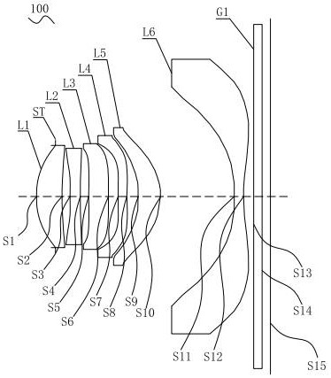
[0072] For the structural schematic diagram of the optical lens 100 provided by the first embodiment of the present invention, please refer to figure 1 , the optical lens includes sequentially from the object side to the imaging surface along the optical axis: a stop ST, a first lens L1, a second lens L2, a third lens L3, a fourth lens L4, a fifth lens L5, a sixth lens L6 and Infrared filter G1.
[0073] The first lens L1 is a plastic aspheric lens with positive refractive power, the object side S1 of the first lens is a convex surface, and the image side S2 of the first lens is a concave surface;
[0074] The second lens L2 is a plastic aspheric lens with negative refractive power, the object side S3 of the second lens is concave, and the image side S4 of the second lens is concave;
[0075] The third lens L3 is a plastic aspheric lens with positive refractive power, the object side S5 of the third lens is convex at the near optical axis, and the image side S6 of the third l...
no. 2 example
[0093] For the structural schematic diagram of the optical lens 200 provided by the second embodiment of the present invention, please refer to Figure 6 , the optical lens includes sequentially from the object side to the imaging surface along the optical axis: a stop ST, a first lens L1, a second lens L2, a third lens L3, a fourth lens L4, a fifth lens L5, a sixth lens L6 and Infrared filter G1.
[0094]The first lens L1 is a plastic aspheric lens with positive refractive power, the object side S1 of the first lens is a convex surface, and the image side S2 of the first lens is a concave surface;
[0095] The second lens L2 is a plastic aspheric lens with negative refractive power, the object side S3 of the second lens is concave, and the image side S4 of the second lens is concave;
[0096] The third lens L3 is a plastic aspheric lens with positive refractive power, the object side S5 of the third lens is convex at the near optical axis, and the image side S6 of the third ...
no. 3 example
[0114] For the structural schematic diagram of the optical lens 300 provided by the third embodiment of the present invention, please refer to Figure 11 , the optical lens includes sequentially from the object side to the imaging surface along the optical axis: a stop ST, a first lens L1, a second lens L2, a third lens L3, a fourth lens L4, a fifth lens L5, a sixth lens L6 and Infrared filter G1.
[0115] The first lens L1 is a plastic aspheric lens with positive refractive power, the object side S1 of the first lens is a convex surface, and the image side S2 of the first lens is a concave surface;
[0116] The second lens L2 is a plastic aspheric lens with negative refractive power, the object side S3 of the second lens is concave, and the image side S4 of the second lens is concave;
[0117] The third lens L3 is a plastic aspheric lens with positive refractive power, the object side S5 of the third lens is a convex surface at the near optical axis, and the image side S6 of...
PUM
 Abstract
Description
Claims
Application Information
 - R&D
- Intellectual Property
- Life Sciences
- Materials
- Tech Scout
- Unparalleled Data Quality
- Higher Quality Content
- 60% Fewer Hallucinations
Browse by: Latest US Patents, China's latest patents, Technical Efficacy Thesaurus, Application Domain, Technology Topic, Popular Technical Reports.
© 2025 PatSnap. All rights reserved.Legal|Privacy policy|Modern Slavery Act Transparency Statement|Sitemap|About US| Contact US: help@patsnap.com