
Measurement apparatus and method for display panel including optical element

A technology of optical components and measuring equipment, which is applied in the directions of optics, measuring electronics, and measuring devices, can solve the problems of taking a long time to measure array units and high economic burden of high-cost current sources, so as to prevent the reduction of measurement speed and reduce power consumption. consumption effect

Pending Publication Date: 2021-08-13
普适福了有限公司
View PDF2 Cites 0 Cited by
  • Summary
  • Abstract
  • Description
  • Claims
  • Application Information

AI Technical Summary

Problems solved by technology

At this time, in the former case, it takes a lot of time to measure all the array elements, and in the latter case, the economic burden of using a high-cost current source is very high

Method used


Image

  • Measurement apparatus and method for display panel including optical element
  • Measurement apparatus and method for display panel including optical element
  • Measurement apparatus and method for display panel including optical element

Examples


Embodiment Construction

[0028] A detailed description of the invention will be made later with reference to the accompanying drawings, which show specific embodiments in which the invention can be practiced to clarify the objects, technical solutions, and advantages of the invention. The detailed description of these embodiments is sufficient to enable those skilled in the art to practice the invention. However, only for the purpose of describing the embodiment according to the present invention and the embodiment according to the concept of the present invention, the specific structure and function description of the embodiment according to the concept and principle of the present invention described in this specification are exemplified, and They can be implemented in various forms, and it can be said that they are not necessarily limited to the embodiments described herein.

[0029] In addition, throughout the detailed description and claims of the present invention, the term "comprising" and its ...


PUM


Abstract

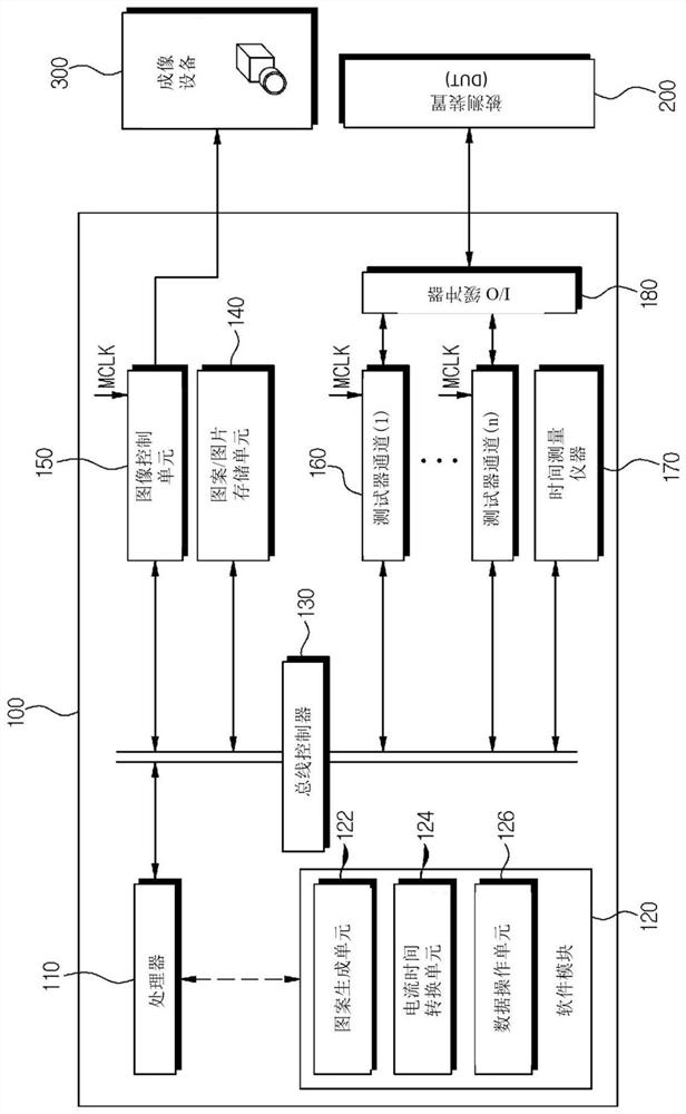
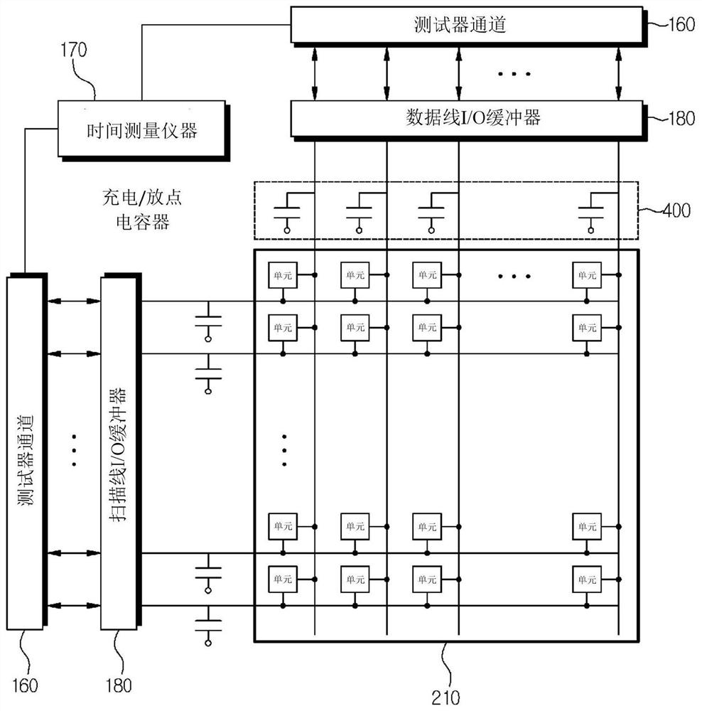
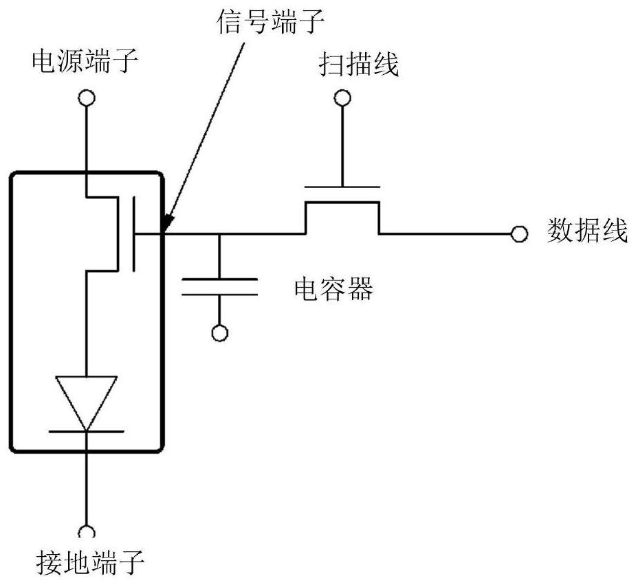
The present invention relates to a measurement apparatus for performing a measurement on a device under test comprising a cell array of optical elements, the measurement apparatus comprising: a capacitor connected in parallel with signal terminals of the cell array of the optical elements; an I / O buffer that increases or decreases an amount of charge of the capacitor by charging or discharging of the capacitor, and outputs a signal corresponding to an output logic value according to a voltage at one end of the capacitor; a time measuring instrument for measuring an arrival time, the arrival time being a time when the voltage at one end of the capacitor reaches a predetermined second voltage from a predetermined first voltage; and a processor that measures the time of arrival by controlling the input I / O buffer and the time measuring instrument, and measures a value of a current related to measurement of the cell array of the optical elements by using the time of arrival, and measures whether the cell array of the optical elements is defective based on the measured value.

Description

technical field [0001] The present invention relates to a measuring device and method for measuring the operating characteristics of a cell array composed of optical elements such as LCD or LED displays or semiconductor elements and detecting defects of the elements. Background technique [0002] Generally, in order to provide a measurement pattern for measuring operation characteristics of a cell array composed of an optical element such as an LCD or an LED display or a semiconductor element and detect a defect of the element, a pattern generating device and an array driving device are required. [0003] In this regard, as disclosed in Korean Patent Application Laid-Open No. 10-0839942, a conventional pattern generating device is composed of expensive hardware such as a pattern file matching unit and a block generating unit, causing a large economic burden. [0004] In addition, as disclosed in US Pat. No. 6,433,485, a conventional array driving device employs a method of a...

Claims


Application Information

Patent Timeline
Patent Type & Authority Applications(China)
IPC IPC(8): G01R31/26G02F1/13
CPCG01R31/2601G02F1/1309G09G3/006G01R31/2635G09G2330/12
Inventor 金秉圭金秉润
Owner 普适福了有限公司
Learn More