A landing light drive mechanism
What is Al technical title?
Al technical title is built by PatSnap Al team. It summarizes the technical point description of the patent document.
A technology of driving mechanism and landing light, applied in the direction of transmission box, transmission device, mechanical equipment, etc., can solve the problems of increasing the air resistance of the aircraft, large overall structure size, large gear gap, etc., and achieves compact structure, not easy to wear, and weight. light effect
Active Publication Date: 2022-07-01
SHANGHAI AEROSPACE SYST ENG INST
View PDF6 Cites 0 Cited by
Summary
Abstract
Description
Claims
Application Information
AI Technical Summary
This helps you quickly interpret patents by identifying the three key elements:
Problems solved by technology
Method used
Benefits of technology
Problems solved by technology
Existing landing light drive mechanisms have many disadvantages
In particular, the existing landing light driving mechanism uses ordinary gears for transmission. In order to achieve a certain output torque requirement, the overall structural size is too large, which increases the air resistance of the aircraft.
Another disadvantage of ordinary gear transmission is that the heavily loaded gears wear out quickly, and the gear gap becomes larger, resulting in obvious shaking of the landing lights, which cannot provide stable lighting for the driver.
Method used
Image
Click on the blue label to locate the original text in one second.
Reading with bidirectional positioning of images and text.
Examples
Embodiment 1
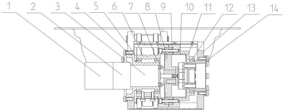
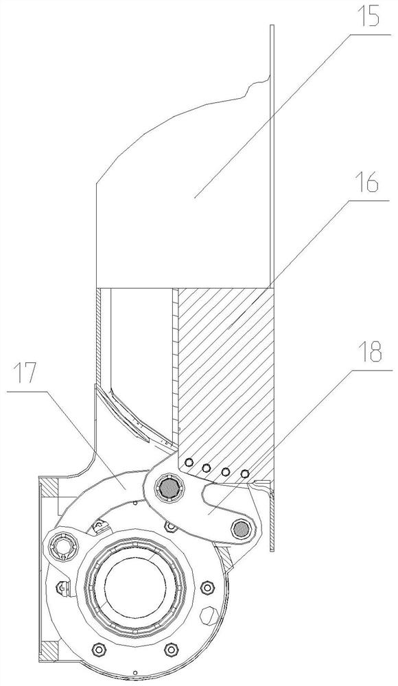
[0023] see figure 1 , The driving mechanism of the landing light in this embodiment includes a motor 1, a brake 2, a planetary reducer 3, a front fixed end cover 4, a bearing 5, a front transmission hollow shaft 6, a bearing 7, a harmonic reducer wave generator 8, a harmonic wave Reducer wave steel wheel 9, harmonic reducer flexible wheel 10, rear drive hollow shaft 11, bearing 12, structural frame 13, rear fixed end cover 14, lampshade 15, lamp holder 16, connecting rod 17, connecting corner block 18
[0024] The end cover 4 is fixed before being installed on the structural frame 13, and the end cover 14 is fixed after being installed on the structural frame 13;
[0025] The planetary reducer 3 installed on the front fixed end cover 4 , the brake 2 fixed with the planetary reducer 3 , and the motor 1 fixed with the brake 2 .
[0026] The output shaft of the planetary reducer 3 is fixedly connected with the harmonic reducer wave generator 8; the harmonic reducer steel wheel 9...
PUM
Abstract
The invention provides a driving mechanism for a landing light, which includes a motor, a brake, a planetary reducer, a front fixed end cover, a first bearing, a front transmission hollow shaft, a second bearing, a harmonic reducer wave generator, and a harmonic reducer wave generator. Steel wheel, harmonic reducer flexible wheel, rear drive hollow shaft, third bearing, structural frame, rear fixed end cover, lampshade, lamp holder, connecting rod and connecting corner block. In the present invention, the harmonic reducer, planetary reducer, etc. are placed inside the driving mechanism of the landing light, so that the driving mechanism of the landing light has a simple structure, a small number of parts, small volume, compact structure and light weight; The reduction ratio is large, the bearing capacity is high, the transmission efficiency is high, the operation is stable, the gear gap is small, and the transmission precision is high. Under the action of long-term load, the gear is not easy to wear, and the landing light will not shake.
Description
technical field [0001] The invention relates to the field of lamp driving mechanisms, in particular to a landing lamp driving mechanism. Background technique [0002] Landing lights are installed on the aircraft to illuminate the area in front of the aircraft when the aircraft is operating at night on taxiways and runways. When not in use, the landing lights can be stowed flush with the outer surface of the aircraft, reducing the aircraft's air resistance. Existing landing light drive mechanisms suffer from a number of disadvantages. In particular, the existing driving mechanism of the landing light uses common gears for transmission, so that in order to achieve a certain output torque requirement, the overall structure size is too large, which increases the air resistance of the aircraft. Another disadvantage of ordinary gear transmission is that the gears under heavy load wear out quickly, and the larger gear gap causes the landing lights to shake obviously, which cannot...
Claims
Application Information
Patent Timeline
Application Date:The date an application was filed.
Publication Date:The date a patent or application was officially published.
First Publication Date:The earliest publication date of a patent with the same application number.
Issue Date:Publication date of the patent grant document.
PCT Entry Date:The Entry date of PCT National Phase.
Estimated Expiry Date:The statutory expiry date of a patent right according to the Patent Law, and it is the longest term of protection that the patent right can achieve without the termination of the patent right due to other reasons(Term extension factor has been taken into account ).
Invalid Date:Actual expiry date is based on effective date or publication date of legal transaction data of invalid patent.