Inertia energy feedback vibration isolation system for intelligent vehicle

A vibration isolation system and smart car technology, applied in the direction of machines/engines, flywheels, mechanical equipment, etc., can solve the problems of failure to realize vibration energy recovery, stay, vibration isolation performance limitations, etc., to achieve strong variability and work stability Strong, simple device structure

Inactive Publication Date: 2021-08-10
JIANGSU UNIV
View PDF7 Cites 0 Cited by
  • Summary
  • Abstract
  • Description
  • Claims
  • Application Information

AI Technical Summary

Problems solved by technology

However, with the emergence of new liquid materials such as magnetorheological fluids and electrorheological fluids, and the increasing advancement of air spring technology, the controllability of the spring stiffness and damping coefficient has been realized in engineering, while the inerter is still in the passive and invariable stage. , the improvement of vibration isolation performance is limited
[0004] Chinese patent 201811602814.7 discloses a magnetorheological fluid inertial device and a continuous adjustment method for its inertial coefficient. It changes the size of the inertial coefficient by changing the magnitude of the magnetic current, and realizes the variable inertial coefficient. However, it does not Capable of recovering vibration energy

Method used


Image

  • Inertia energy feedback vibration isolation system for intelligent vehicle
  • Inertia energy feedback vibration isolation system for intelligent vehicle

Examples


Embodiment Construction

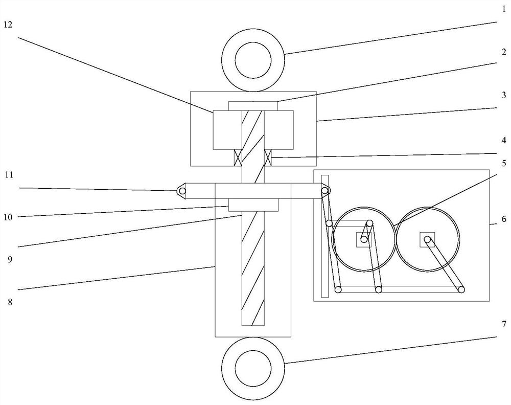
[0015] An inertial energy feed vibration isolation system for smart vehicles proposed by the present invention mainly includes: upper lifting lug 1, compression nut 2, flywheel chamber 3, bearing 4, gear a5, box body 6, lower lifting lug 7, stroke chamber 8 , ball screw 9, screw nut 10, hinge 11, flywheel 12, connection point g13, connection point a14, gear b15, rod a16, connection point b17, rod b18, connection point c19, connection point d20, rod e21, connection Point h22, rod c23, rod f24, connection point e25, rod d26, connection point f27.

[0016] The structural schematic diagram of the inertial energy feeding vibration isolation system for a smart vehicle is as follows: figure 1 As shown, wherein: the upper lug 1 is hinged with the flywheel chamber 3, the upper end of the ball screw 9 is engaged with the compression nut 2, and the compression nut 2 restricts the flywheel 12 in the flywheel chamber 3, and the flywheel 12 and the ball screw 9 pass through The keys are co...


PUM


Abstract

The invention discloses an inertial energy feedback vibration isolation system for an intelligent vehicle. According to the inertial energy feedback vibration isolation system, through matching of different devices on an inner gear of an energy feedback device, change of inertial coefficients or energy recovery is achieved. Through different matching of a flywheel and a motor on the inner gear of the energy feedback device, change of the inertial coefficients of the three levels of large, medium and small and the energy recovery degrees of the two degrees of strong and weak can be achieved, the principle is simple, and the scheme is easy to implement. According to the scheme, the engineering application problem that energy of a mechanical inertial container is difficult to recover is solved, the structure is simple, and the practical application value is achieved.

Description

technical field [0001] The invention relates to an inertial energy feeding vibration isolation system for smart vehicles, in particular to a vibration isolation system coupled by a mechanical ball screw inerter and a vibration energy recovery device. Background technique [0002] The concept of "inertia" was first proposed by the Smith scholars of the University of Cambridge, UK. Based on the second type of electromechanical similarity theory of "force-current", the inertial vessel is defined as a two-terminal element. proportional to the relative acceleration of the endpoints. Its dynamic expression is: F is the force exerted on the two ends of the inerter, v 1 , v 2 is the speed of both ends, b is defined as the inertia coefficient, which is an important physical quantity to characterize the inerter. [0003] The birth of the inerter solves the single-end problem that the mass element must take the center of the earth as the reference system. The new mechanical vibrat...

Claims


Application Information

Patent Timeline
Patent Type & Authority Applications(China)
IPC IPC(8): F03G7/08F16F15/30
CPCF03G7/08F16F15/30
Inventor 沈钰杰曹瑞阳杨斤澎蒋睿葛予涵陈龙杨晓峰
Owner JIANGSU UNIV
Why Eureka
Try Eureka