Two-way vent valve of inner floating roof

A two-way ventilation valve and inner floating roof technology, applied in the direction of containers, packaging, transportation and packaging, etc., can solve problems such as unsmooth travel, inability to adjust gas and pressure, difficult to open the cover plate 13, etc., to reduce the area of ​​friction , Improve sliding smoothness, reduce mutual friction effect

Active Publication Date: 2021-08-06
CHING KAI ENTERPRISE CO LTD
View PDF5 Cites 1 Cited by
  • Summary
  • Abstract
  • Description
  • Claims
  • Application Information

AI Technical Summary

Problems solved by technology

[0005] However, the breather valve 1 can only be opened when the pillar 12 touches the inner bottom surface 3 of the liquid storage tank, and the gas and pressure cannot be adjusted in situations other than the maintenance height.
When the pillar 12 moves up and down, the entire outer peripheral surface will rub against the inner surrounding wall 113 of the outer frame base 11, and the friction area is too large, causing the pillar 12 made of metal and the inner wall 113 to The surrounding wall 113 is easy to wear, and the problem that the cover plate 13 is difficult to open due to vacuum adsorption
In addition, the prop 12 starts by hitting the inner bottom surface 3 of the liquid storage tank, but generally the inner bottom surface 3 of the liquid storage tank is often uneven, so the prop 12 is easy to touch the bottom due to the non-flat surface of the contact surface. It is skewed, which causes the support 12 to be unable to move up and down in a straight up and down manner, which not only makes the stroke not smooth, but also causes the components of the vent valve 1 to be damaged or unable to operate due to excessive wear and pushing.

Method used


Image

  • Two-way vent valve of inner floating roof
  • Two-way vent valve of inner floating roof
  • Two-way vent valve of inner floating roof

Examples


Embodiment Construction

[0024] The present invention will be described in detail below with reference to the accompanying drawings and embodiments.

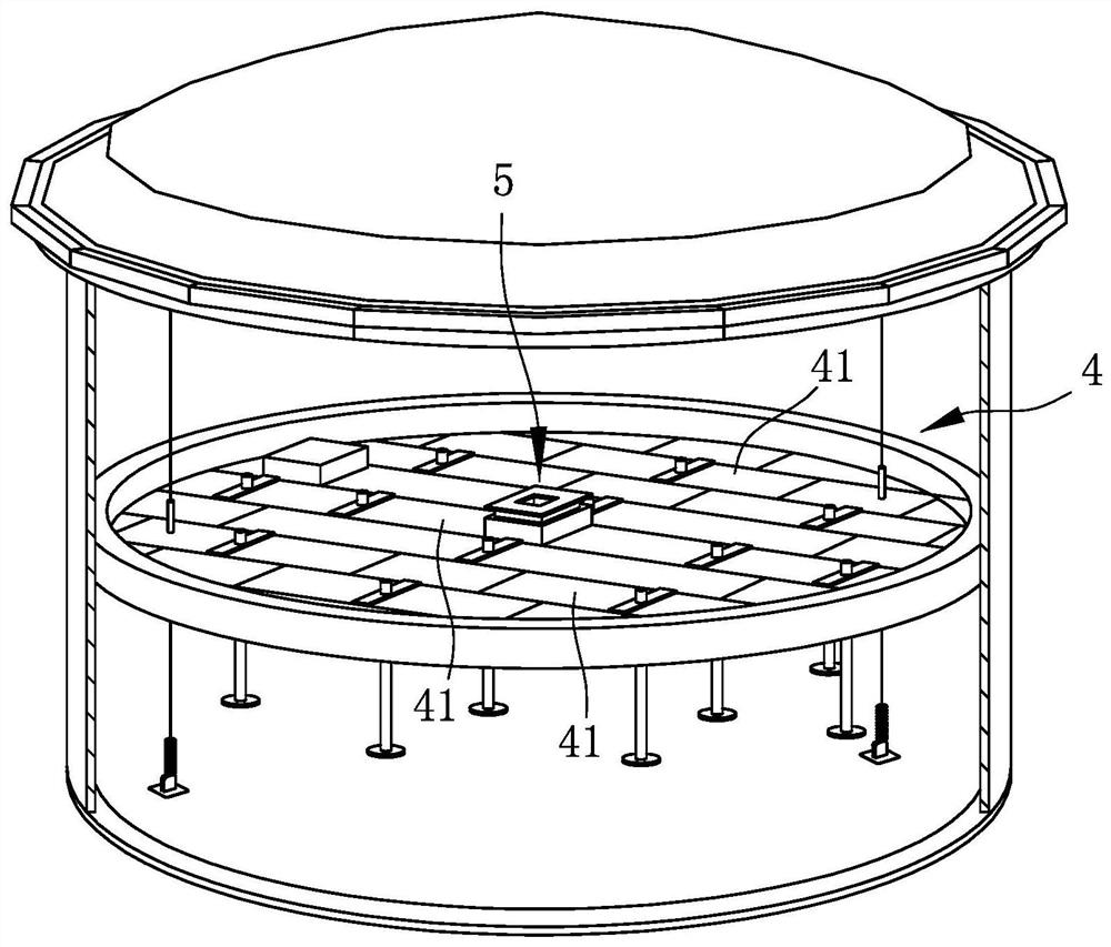
[0025] see image 3 , Figure 4 ,and Figure 5 , an embodiment of the ventilation valve 5 of the inner floating roof 4 of the present invention is suitable for being arranged on an inner floating roof 4 . The ventilation valve 5 includes an outer frame base 51 fixed on the inner floating roof 4, a ventilation hole box 52 surrounded by the outer frame base 51 and forming a plurality of air holes 521, and a ventilation hole box 52 fixed on the outer frame base 51. A sealing cover 53 located on the top surface of the vent box 52 and located above the outer frame base 51, a floating box 54 located below the sealing cover 53, a plurality of air holes disposed on the outer frame base 51, the ventilation holes The sliding member 55 between the box 52 and the floating box 54 , and a plurality of guiding members 56 disposed between the outer frame base 51 , t...


PUM


Abstract

A two-way vent valve of an inner floating roof comprises an outer frame base fixed to the inner floating roof, a sealing cover on the outer frame base, a vent hole box fixed to the lower portion of the sealing cover, a floating box surrounded by the vent hole box and multiple strip-shaped sliding pieces fixed in inner space among the outer frame base, the vent hole box and the floating box. Opening and closing actions are achieved through the pressure difference and the gravitation difference of liquid to the floating force of the floating box, when the liquid level rises, the floating box can push the sealing cover upwards to enable an annular air groove to be opened so as to relieve pressure and achieve ventilation, and when the liquid level falls, the floating box is attracted to open the sealing cover downwards to enable a central opening of the sealing cover to be opened so as to relieve pressure and achieve ventilation. The sliding pieces are made of non-metal materials, and therefore the smoothness degree of a sliding surface is improved, and the problems of temperature, sparks and the like caused by metal friction can be avoided.

Description

technical field [0001] The invention relates to an air valve, in particular to a two-way ventilation valve with an inner floating roof. Background technique [0002] The inner floating roof is used in the storage tank for storing volatile organic compounds. The inner floating roof covers the liquid level of the storage liquid, and rises and falls with the rise and fall of the liquid level, which can greatly reduce the volatilization of the storage liquid. effect. Although the liquid storage tank needs good airtightness to avoid the loss caused by volatilization of the liquid storage tank, in the process of liquid injection and liquid extraction in the liquid storage tank, it is still necessary to generate air flow in the liquid storage tank to facilitate liquid storage. In and out, and at the same time has the function of adjusting the pressure. [0003] see figure 1 and figure 2 , so a ventilation valve 1 is provided on the general inner floating roof. The ventilation...

Claims


Application Information

Patent Timeline
Patent Type & Authority Applications(China)
IPC IPC(8): B65D88/34
CPCB65D88/34
Inventor 潘文斌颜淑文
Owner CHING KAI ENTERPRISE CO LTD
Why Eureka
Try Eureka