Scrap collecting device for machining and using method thereof

A collection device and machining technology, applied in the direction of metal processing equipment, metal processing machine parts, manufacturing tools, etc., can solve the problems of inconvenient handling and reprocessing, different sizes, and uneven shapes of iron scraps, to ensure The layout is reasonable, the compression effect is good, and the layout is compact.

Inactive Publication Date: 2021-08-06
赵伟
View PDF0 Cites 0 Cited by
  • Summary
  • Abstract
  • Description
  • Claims
  • Application Information

AI Technical Summary

Problems solved by technology

In addition, due to the uneven shape and size of iron scrap, simple box collection will temporarily use a large amount of storage space, and it is not convenient for subsequent handling and reprocessing

Method used


Image

  • Scrap collecting device for machining and using method thereof
  • Scrap collecting device for machining and using method thereof
  • Scrap collecting device for machining and using method thereof

Examples


Embodiment Construction

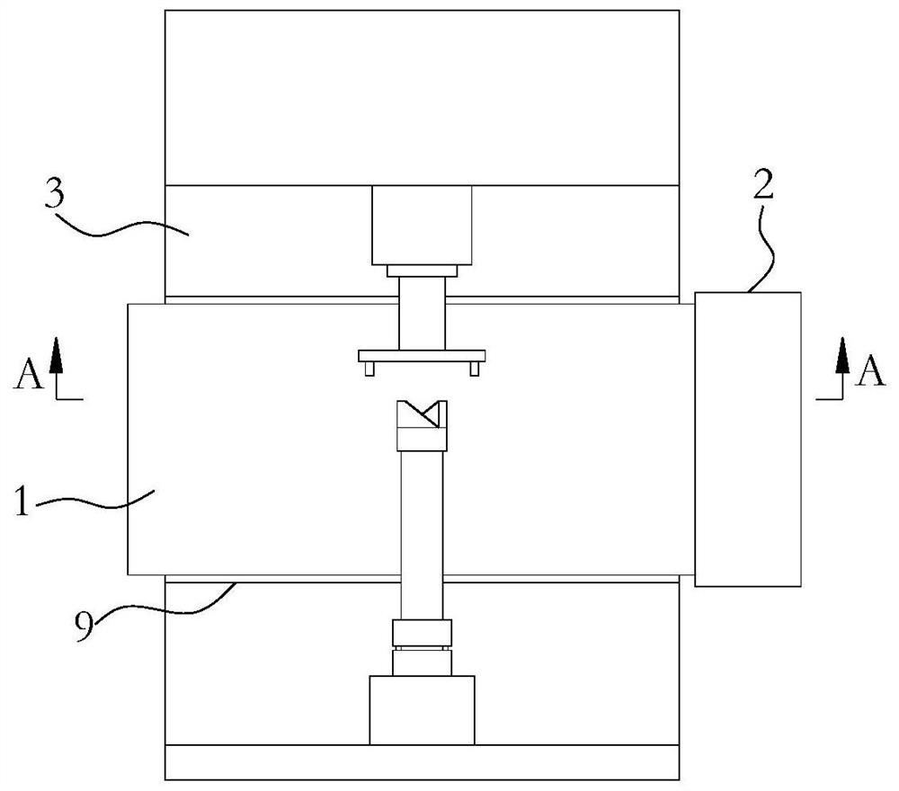
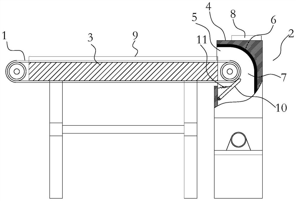
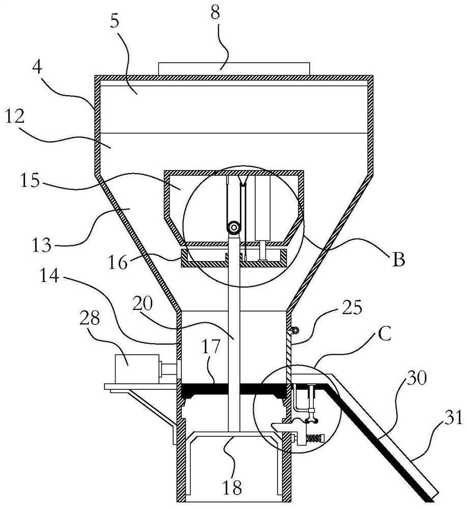
[0035] Such as Figure 1-9 As shown, a chip collection device for machining is installed on the machine tool for collecting and compressing iron filings and iron powder generated by machining. It mainly includes two major components, one part is The conveyor belt 1 for conveying the waste, and the other part is the collection compression box 2 for collecting and compressing the waste. The two cooperate to realize the functions of transportation, collection and compression.

[0036] From the perspective of realizing the transportation and collection of iron filings, such as figure 1 As shown in , the conveyor belt 1 is set at the processing station of the machine tool 3 workbench, for example: as figure 1 As shown in , the machine tool is provided with a fixture and a rotary tool, the workpiece is installed on the fixture, and the rotary tool is used to process the workpiece, and the conveyor belt 1 is located at the station near the fixture and the rotary tool. For ease of ...


PUM


Abstract

The invention relates to the technical field of machining. The invention aims to provide a scrap collecting device for machining. The device comprises a conveying belt used for conveying waste and a collecting and compressing box used for collecting and compressing the waste. The collecting and compressing box comprises a box body, and the box body comprises a feeding chamber, a collecting chamber and a compressing chamber which are sequentially communicated from top to bottom. The collecting chamber is gradually reduced from top to bottom, a mounting area penetrating through the two faces of the collecting chamber is arranged in the middle of the collecting chamber, and a driving mechanism is arranged in the mounting area. An upper pressing plate is arranged in the collecting chamber and below the mounting area, and a lower pressing plate and an inverted-U-shaped lower pushing plate which are in sliding fit with the compressing chamber are arranged in the compressing chamber. According to the device, rapid compression of waste can be achieved, the overall compression effect is better due to the fact that an up-down bidirectional pressurization compression mode is adopted, and follow-up transportation and reprocessing of the waste are facilitated.

Description

technical field [0001] The invention relates to the technical field of machining, in particular to a debris collection device for machining and a method for using the same. Background technique [0002] Machining refers to the process of using machine tools to perform cutting, milling, boring, cutting and other processing operations on mechanical parts. During the machining process, a large amount of waste such as iron filings, iron wires, and iron dust will be generated, which will fall on the processing table. At present, when the traditional method is used to process these waste materials, the operator usually shuts down the machine to remove the waste materials from the processing table when changing shifts. However, this method is time-consuming and laborious, and a lot of time is wasted, which greatly affects the machining efficiency. , especially in some processing conditions, the amount of waste generated is large, and the processing table will be full in a short per...

Claims


Application Information

Patent Timeline
IPC IPC(8): B23Q11/00
CPCB23Q11/0042
Inventor 赵伟
Owner 赵伟
Why Eureka
Try Eureka