
Cutting device capable of accurately cutting steel plate and cutting method thereof

A technology for cutting devices and steel plates, applied in feeding devices, positioning devices, manufacturing tools, etc., can solve the problems of irregular cutting edges of steel plates, affect steel plate processing, and low production efficiency, and achieve the effect of neat cutting edges and improved production efficiency

Active Publication Date: 2021-08-06
泰州润骐防务科技有限公司
View PDF8 Cites 0 Cited by
  • Summary
  • Abstract
  • Description
  • Claims
  • Application Information

AI Technical Summary

Problems solved by technology

[0004] The currently used steel plate cutting device, in the process of cutting the steel plate, manually moves the steel plate and performs positioning and cutting, but the above method has the following disadvantages: the manual operation cannot accurately locate the position where the steel plate needs to be cut , the production efficiency is low, and it will also cause the cutting edge of the steel plate to be irregular, which will affect the subsequent processing of the steel plate

Method used


Image

  • Cutting device capable of accurately cutting steel plate and cutting method thereof
  • Cutting device capable of accurately cutting steel plate and cutting method thereof
  • Cutting device capable of accurately cutting steel plate and cutting method thereof

Examples


Embodiment Construction

[0031] The present invention will be further described below in conjunction with the accompanying drawings.

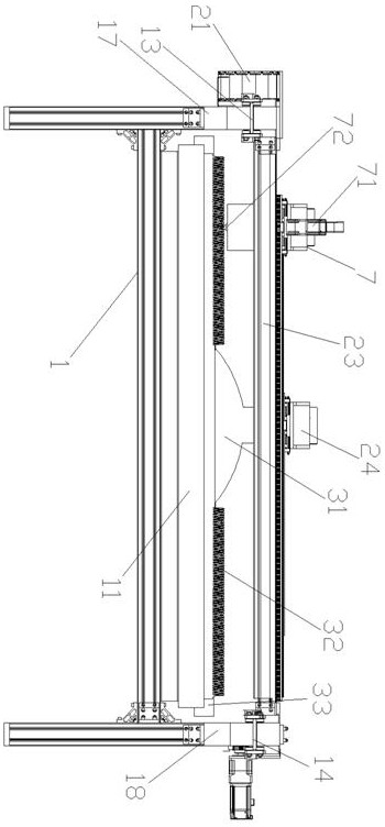
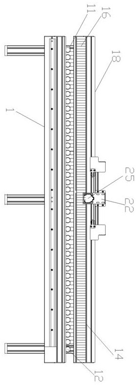
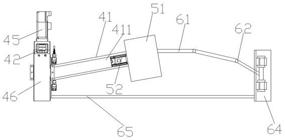
[0032] Such as figure 1 Shown is a schematic left view of a cutting device that can precisely cut steel plates, such as figure 2 Shown is a schematic front view of a cutting device that can accurately cut steel plates, including a workbench 1, a fixing plate is provided on both sides of the workbench 1, a chute 411 is opened on the fixing plate, and a transmission mechanism is also provided on the workbench 1. Steering mechanism, moving mechanism, auxiliary mechanism, cutting mechanism 7 and the adsorption mechanism that absorbs the steel plate to move, the transmission mechanism can be slidably arranged on the workbench 1, the adsorption mechanism is arranged on the transmission mechanism, and the steering mechanism cooperates with the auxiliary mechanism And it can be slidably arranged on the workbench 1, the moving mechanism can be slidably arranged on the steerin...


PUM


Abstract

The invention discloses a cutting device capable of accurately cutting a steel plate and a cutting method thereof. The cutting device comprises a working table. Fixing plates are arranged on the two sides of the working table. Sliding grooves are formed in the fixing plates. The working table is provided with a transmission mechanism, a steering mechanism, a moving mechanism, an auxiliary mechanism, a cutting mechanism and an adsorbing mechanism for adsorbing and moving the steel plate. The transmission mechanism is arranged on the working table in a sliding manner. The adsorbing mechanism is arranged on the transmission mechanism. The steering mechanism is arranged on the working table in a sliding manner by mutually cooperating with the auxiliary mechanism. The moving mechanism is arranged on the steering mechanism in a sliding manner. The cutting mechanism is fixed to the moving mechanism. The adsorbing mechanism and the cutting mechanism are arranged on the working table side by side. According to the cutting device, the transmission mechanism drives the steel plate to move, the steering mechanism and the auxiliary mechanism mutually cooperate, the moving mechanism on the steering mechanism drives the cutting device to move and cut, the position, needing to be cut, of the steel plate is cut accurately, the production efficiency is improved, and the cut edge of the steel plate is neat.

Description

technical field [0001] The invention relates to the technical field of cutting, in particular to a cutting device capable of precisely cutting steel plates and a cutting method thereof. Background technique [0002] Metal cutting refers to the use of natural gas flame (oxygen-natural gas) to preheat the metal to be cut to the ignition point where it can burn or become soft, and then release a high-pressure oxygen flow to further violently oxidize the metal and blow off the slag produced by combustion to form The process of incision. As a very important metal processing and treatment method, metal cutting has been applied in many technical fields at present, and is a very important, well-known and widely used technical method. In metal cutting, steel plate cutting is a very important category. [0003] Because steel has great coverage and containment capacity, it is the most widely used and common. It can be used as roof panels, thatch materials, and manufacturing container...

Claims


Application Information

Patent Timeline
Patent Type & Authority Applications(China)
IPC IPC(8): B23D79/00B23Q3/06B23Q5/26B23Q7/04B23Q17/22
CPCB23D79/00B23Q7/043B23Q3/062B23Q5/26B23Q17/22Y02P70/10
Inventor 刘戈刘金旭贺川蒋华敏蒋明李斌张存宝
Owner 泰州润骐防务科技有限公司
Learn More