Automatic networking equipment and steel mesh cage processing system

An automatic networking and equipment technology, applied to wire processing, metal processing equipment, wire netting, etc., can solve the problems of lower networking efficiency, low efficiency, and lower production efficiency of autoclaved aerated concrete slabs, so as to improve connection efficiency , The effect of improving assembly efficiency

Active Publication Date: 2022-07-19
GUANGDONG BOZHILIN ROBOT CO LTD
View PDF6 Cites 0 Cited by
  • Summary
  • Abstract
  • Description
  • Claims
  • Application Information

AI Technical Summary

Problems solved by technology

[0003] In the prior art, the assembly of the steel mesh cage is generally completed manually by the buckle and the assembly of the steel braze, and then the single piece of steel mesh is combined into a steel mesh cage through the buckle connection manually. This is done manually. The efficiency of the networking method is low, and it requires the cooperation of multiple people to complete, thereby reducing the networking efficiency of a single piece of steel mesh assembled into a steel mesh cage, thereby reducing the production efficiency of the entire autoclaved aerated concrete slab

Method used


Image

  • Automatic networking equipment and steel mesh cage processing system
  • Automatic networking equipment and steel mesh cage processing system
  • Automatic networking equipment and steel mesh cage processing system

Examples


Embodiment 1

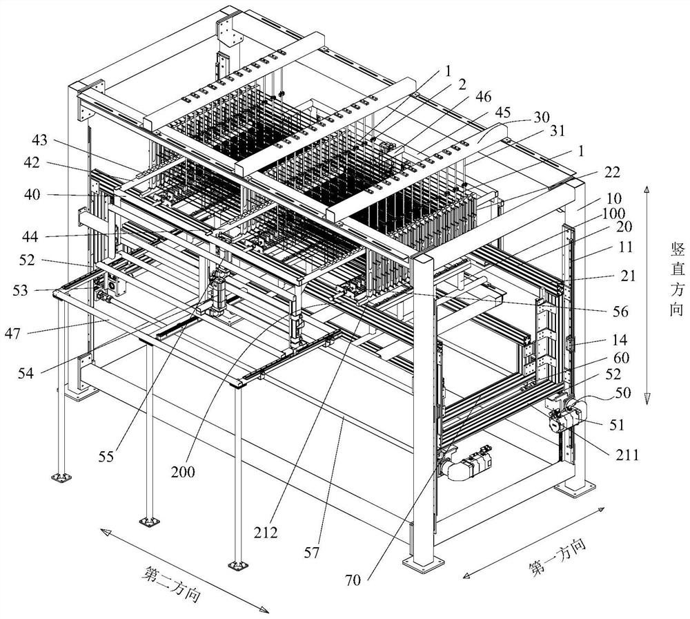
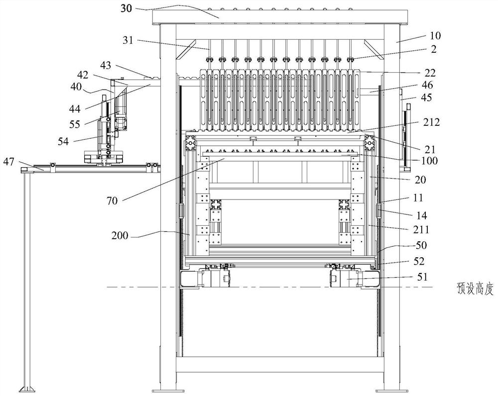
[0049] like figure 1 and figure 2 As shown, an embodiment of the present invention provides an automatic networking device. The automatic networking equipment includes a workpiece support 30 , a workpiece mounting mechanism 100 , a networking mechanism 200 , a mesh lifting mechanism 50 and a first cantilever structure 40 . Wherein, the workpiece support 30 has a storage space for storing a plurality of steel rods; the workpiece mounting mechanism 100 includes a snap support device 70 with a plurality of mounting holes 713, and at least part of the workpiece mounting mechanism 100 is vertically movable up and down. Driven by at least part of the workpiece mounting mechanism 100 , the buckle supporting device 70 and the buckle 2 located in each installation hole 713 can move to a preset position corresponding to the steel drill 31 in the vertical direction, so as to install the buckle 2 on the Steel drill 31; the networking mechanism 200 includes a mesh support structure 20 f...

Embodiment 2

[0145] Different from the first example, as Figure 10As shown, in the second embodiment of the present invention, the first cantilever structure 40 includes two first cantilever portions 42 with a predetermined distance. Likewise, the second cantilever structure 45 includes two second cantilever parts 46 with a preset distance. The second cantilever parts 46 are used to support the first cantilever part 42 and prevent the first cantilever part 42 from being deformed to ensure better The longitudinal ribs that support the mesh.

[0146] It should be noted that the setting of the preset distance needs to ensure that the two first cantilever portions 42 can simultaneously support the outermost longitudinal ribs of the mesh sheet (ie, the uppermost longitudinal ribs and the lowermost longitudinal ribs). For example, the preset distance can be set to be equal to the vertical distance between the outermost longitudinal ribs of the mesh sheet, so that by lifting the entire first ca...

Embodiment 3

[0149] Different from the first example, as Figure 11 As shown, the networking mechanism 200 includes two first cantilever structures 40 and two second cantilever structures 45 corresponding to the two first cantilever structures 40 . The uppermost longitudinal rib and the lowermost longitudinal rib of the sheet are supported.

[0150] In this way, two second driving structures 55 also need to be provided, so that the two first cantilever structures 40 can be driven away from each other, so as to simultaneously clip the mesh into the upper buckle and the lower buckle. Automate the networking process.

[0151] Other structures in the third embodiment are the same as those in the first embodiment, and are not repeated here.


PUM


Abstract

The invention provides an automatic networking equipment and a steel mesh cage processing system. Automatic networking equipment, including: a workpiece support; a workpiece installation mechanism, including a buckle support device with a plurality of installation holes, at least part of the workpiece installation mechanism can be set up and down in a vertical direction; a network mechanism, including a mesh for accommodating At least part of the mesh supporting structure is set up and down in the vertical direction; the mesh lifting mechanism is used to drive part of the mesh supporting structure to move in the vertical direction; the first cantilever structure is located at the bottom of the mesh lifting mechanism. On one side, the first cantilever structure includes a first cantilever portion, and the first cantilever portion is movably arranged along the vertical direction and the first direction, so that at least part of the first cantilever portion can be penetrated in the mesh and aligned at constant intervals. At least one pair of longitudinal ribs of the mesh sheet is supported, and driven by the first cantilever portion, the mesh sheet is clamped with the buckle. In the technical scheme of the present invention, the automatic networking equipment can improve the networking efficiency of workpieces such as mesh sheets.

Description

technical field [0001] The invention relates to the field of reinforcement mesh cage forming, in particular to an automatic networking equipment and a reinforcement mesh cage processing system. Background technique [0002] In the production process of autoclaved aerated concrete panels, reinforcement mesh cages need to be added to the panels to strengthen their structural stability. Insert the casting mould box on the steel rod. [0003] In the prior art, the assembling of the steel mesh cage is generally done manually by assembling the buckles and the steel brazing, and then the single piece of steel mesh is manually assembled into a steel mesh cage through the buckle connection. This is done manually. The efficiency of the networking method is low, and it requires the cooperation of many people to complete, which reduces the networking efficiency of a single piece of reinforced mesh to form a reinforced mesh cage, thereby reducing the production efficiency of the entire ...

Claims


Application Information

Patent Timeline
Patent Type & Authority Patents(China)
IPC IPC(8): B21F27/20B21F33/00
CPCB21F27/20B21F33/007
Inventor 邬全兵李小龙张琼
Owner GUANGDONG BOZHILIN ROBOT CO LTD
Why Eureka
Try Eureka