


Quick Research
Generate reliable direction feasibility study reports for your R&D in just a few steps.

Technical Q&A
Discover and master advanced knowledge NOW. Basics, ideas, possibilities, all at once.

Find Solutions
As an expert in R&D theories, this can generate solutions to your technical problems instantly.

Evaluate Feasibility
Analyze your overall solution with one click, know your potential R&D risks in advance.

Monitor Landscape
Get weekly tech updates, stay abreast of the latest tech innovations and key insights.
Comprehensive therapeutic apparatus for amblyopia and myopia
A comprehensive treatment and myopia technology, applied in the field of medical devices, can solve the problem that the single light source system cannot switch between different treatment modes, and achieve the effects of cost saving, soft material and simple design structure
- Summary
- Abstract
- Description
- Claims
- Application Information
AI Technical Summary
Problems solved by technology
Method used
Image

Examples
Embodiment 1
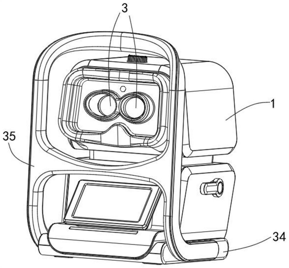
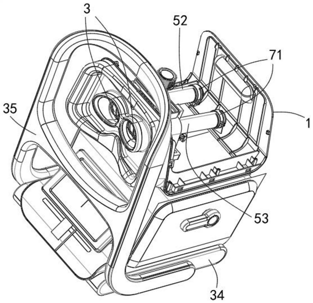
[0052] Example 1, please refer to figure 1 and figure 2 , the present invention provides an embodiment of a comprehensive therapeutic apparatus for amblyopia and myopia, which includes an outer shell 1, an optical path tube, and a multi-light source emitting device 71. The outer shell 1 packs most of the parts of the therapeutic apparatus into itself to play a role in installation. The function of support and protection, the outer casing 1 is provided with a viewing window 3, the viewing window 3 allows the user to look into the interior of the outer casing 1 from the outside of the outer casing 1, and the optical path tube includes The first optical path barrel 52 and the second optical path barrel 53, the first optical path barrel 52 and the second optical path barrel 53 are arranged in parallel inside the outer shell 1, the first optical path barrel 52 and the second optical path barrel 53 The optical path cylinder 53 can adjust the relative distance by controlling, there...
Embodiment 2
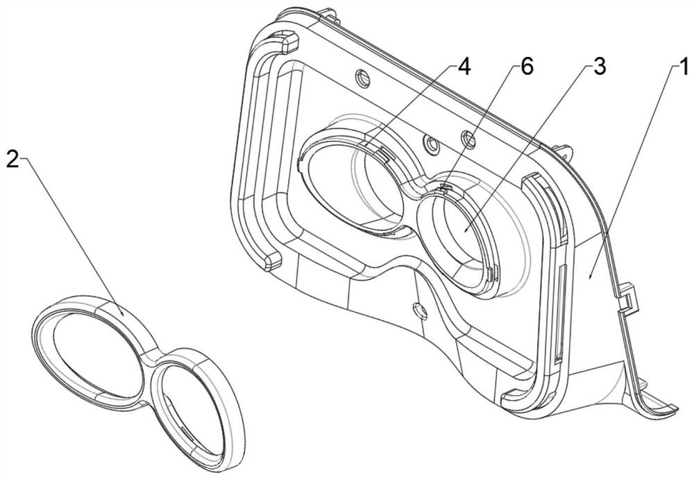
[0053] Example 2, please refer to image 3 and Figure 4 , the orbital pad 2 is detachably installed on the edge of the viewing window 3, the orbital pad 2 is made of soft material, the material of the orbital pad 2 can be selected from materials such as silica gel or rubber, and the material is soft and It is more friendly to the user's skin; the edge of the viewing window 3 can be provided with a rib structure 4, and one side of the orbital pad 2 can be provided with a groove 5, and the other side of the orbital pad 2 is used for contact with the user. Contact, the rib structure 4 can be embedded in the groove 5; the side of the rib structure 4 can be provided with a clip 6, the outer side of the clip 6 is a guide side, and the guide side The surface of the surface can be an arc or an inclined surface. One side of the inner side of the clamp 6 is a locking side, the guiding side is a small end, the locking side is a large end, and the inner side wall of the groove 5 A card...
Embodiment 3
[0054] Embodiment 3, the orbital pad 2 is non-detachable and installed on the edge of the viewing window 3. The specific non-detachable method can be molded integrally, or by riveting, or by gluing and other forms to complete the installation. This non-detachable The design of the dismounting installation method is conducive to the stability of the instrument structure and reduces the difficulty of equipment processing. The orbital pad 2 is made of soft materials, and the material of the orbital pad 2 can be selected from materials such as silica gel or rubber. Softer and more friendly to the user's skin.
PUM
| Property | Measurement | Unit |
|---|---|---|
| Arc angle | aaaaa | aaaaa |
Abstract
Description
Claims
Application Information
 - R&D Engineer
- R&D Manager
- IP Professional
- Industry Leading Data Capabilities
- Powerful AI technology
- Patent DNA Extraction
Browse by: Latest US Patents, China's latest patents, Technical Efficacy Thesaurus, Application Domain, Technology Topic, Popular Technical Reports.
© 2024 PatSnap. All rights reserved.Legal|Privacy policy|Modern Slavery Act Transparency Statement|Sitemap|About US| Contact US: help@patsnap.com