An air conditioning mechanism for building floors

A technology for air conditioning and buildings, applied in air humidification systems, applications, mechanical equipment, etc., can solve problems such as waste of resources, long-term use of power equipment, and easy loss

Active Publication Date: 2022-03-01
上海皓科建设集团有限公司
View PDF0 Cites 0 Cited by
  • Summary
  • Abstract
  • Description
  • Claims
  • Application Information

AI Technical Summary

Problems solved by technology

[0003] However, most of the existing floor air-conditioning mechanisms use electric equipment to drive the fan, so that the air intake and outlet pipes in the air-conditioning mechanism can replace the air between floors, and the air-conditioning mechanism needs to run for a long time , it is easy to lead to long-term use of power equipment, which consumes energy and is easy to lose, resulting in frequent replacement and wasting resources

Method used


Image

  • An air conditioning mechanism for building floors
  • An air conditioning mechanism for building floors
  • An air conditioning mechanism for building floors

Examples


Embodiment 1

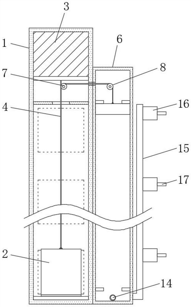
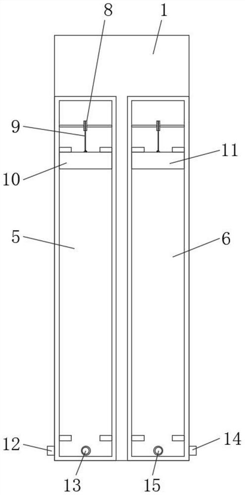
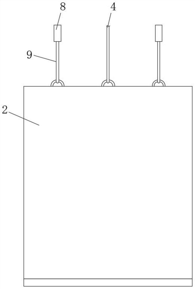
[0027]An air conditioning mechanism for building floors, the air conditioning mechanism is located on one side of the elevator shaft 1, the interior of the elevator shaft 1 is provided with a car 2 and a machine room 3, and the interior of the machine room 3 is provided with a traction machine, and the traction The machine is fixedly connected to the top of the car 2 through a rope 4. The air conditioning mechanism includes a first chamber 5 and a second chamber 6 located on one side of the elevator shaft 1. Roller 7, and the number of the first roller 7 is two, the inner top of the first chamber 5 and the second chamber 6 are all rotatably connected with the second roller 8, the inside of the first chamber 5 is located below the second roller 8 A first counterweight piston 10 is provided, and the outer peripheral wall of the first counterweight piston 10 is in close contact with the inner peripheral wall of the first chamber 5, and a second counterweight is arranged inside the...

Embodiment 2

[0035] Please focus on Figure 6 and 7 , The difference between this embodiment and Embodiment 1 is that: the top of the first chamber 5 is provided with a water pipe 23 penetrating to the inside of the first chamber 5, and the inside of the water pipe 23 is fixedly connected with a fixing plate 25, and the fixing plate 25 The bottom of the spring 26 is fixedly connected with a spring 26, and the bottom of the spring 26 is fixedly connected with a gasket 27. The inner wall of the water pipe 23 is located below the fixed plate 25 and is fixedly connected with a mounting plate 28, and the middle position of the mounting plate 28 is provided with a through hole 29. The top of a counterweight piston 10 is located at the rear end of the connecting rope 9 and is provided with a pipeline 24. The bottom of the first counterweight piston 10 is provided with an atomizing nozzle 33, and the top of the outside of the pipeline 24 is provided with a water inlet 31. The first counterweight p...


PUM


Abstract

The invention discloses an air conditioning mechanism for building floors, which comprises a first chamber and a second chamber located on one side of an elevator shaft, and a first roller located below a machine room inside the elevator shaft, and the first roller is The number is two, and the inner tops of the first chamber and the second chamber are both rotatably connected with second rollers, and a first counterweight piston is arranged inside the first chamber below the second rollers. The present invention effectively utilizes the up and down movement of the car to replace the air between the floors, and does not need to install any exhaust fan and intake fan in the ventilation system between the floors, and does not need any power equipment, which saves resources and at the same time the first To a certain extent, the counterweight piston and the second counterweight piston did not increase the load of the rope and the traction machine. On the contrary, they effectively decomposed the gravity of the car and reduced the load of the traction machine and rope in the machine room. The heavy load prolongs the service life of the traction machine and ropes inside the machine room.

Description

technical field [0001] The invention relates to the construction field, in particular to an air conditioning mechanism for building floors. Background technique [0002] Conventionally, the air conditioning of spaces in high-rise buildings, ie in buildings with several floors, takes place via a central air conditioning unit, fresh air being sucked in, filtered, centrally, for example via installations on the roof of the building, The humidity is dehumidified, the temperature is adjusted and then distributed to the various floors of the building via the air ducts running in the shaft. [0003] However, most of the existing floor air-conditioning mechanisms use electric equipment to drive the fan, so that the air intake and outlet pipes in the air-conditioning mechanism can replace the air between floors, and the air-conditioning mechanism needs to run for a long time , It is easy to lead to long-term use of power equipment, which consumes energy and is easy to wear and tear,...

Claims


Application Information

Patent Timeline
Patent Type & Authority Patents(China)
IPC IPC(8): F24F7/08F24F13/02F24F6/12F24F11/84
CPCF24F7/08F24F13/02F24F6/12F24F11/84
Inventor 陈阿三
Owner 上海皓科建设集团有限公司
Why Eureka
Try Eureka